Equipment for cold-drawing a metal wire

Active Publication Date: 2007-11-06
VASSENA FILIERE
View PDF11 Cites 1 Cited by
  • Summary
  • Abstract
  • Description
  • Claims
  • Application Information

AI Technical Summary

Benefits of technology

[0008]In view of the state of the technique described, the object of the present invention is to produce equipment for cold-drawing a metal wire that presents greater advantages in terms of mounting and thus overall cost of the equipment.
[0009]In accordance with the present invention, said object is achieved by equipment for cold-drawing a metal wire, said equipment comprising a succession of a sleeve with a cylindrical

Problems solved by technology

Nevertheless, mounting the threading die onto the sleeve can become a complicated operation; in fact this operation sometimes has to be repeated

Method used


Image

  • Equipment for cold-drawing a metal wire
  • Equipment for cold-drawing a metal wire
  • Equipment for cold-drawing a metal wire

Examples


Embodiment Construction

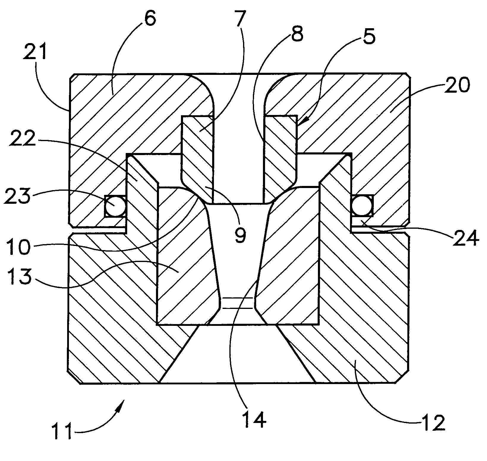
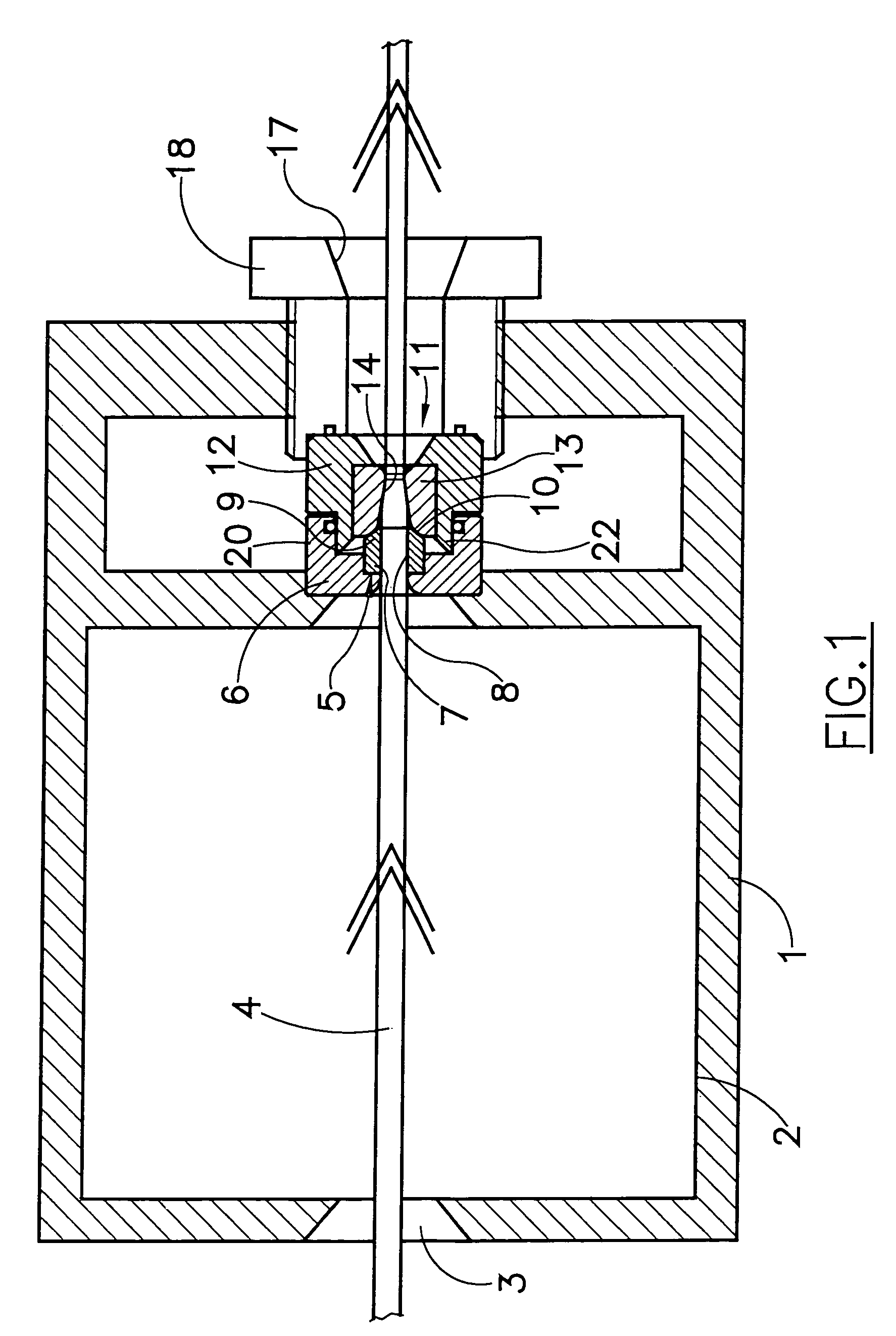
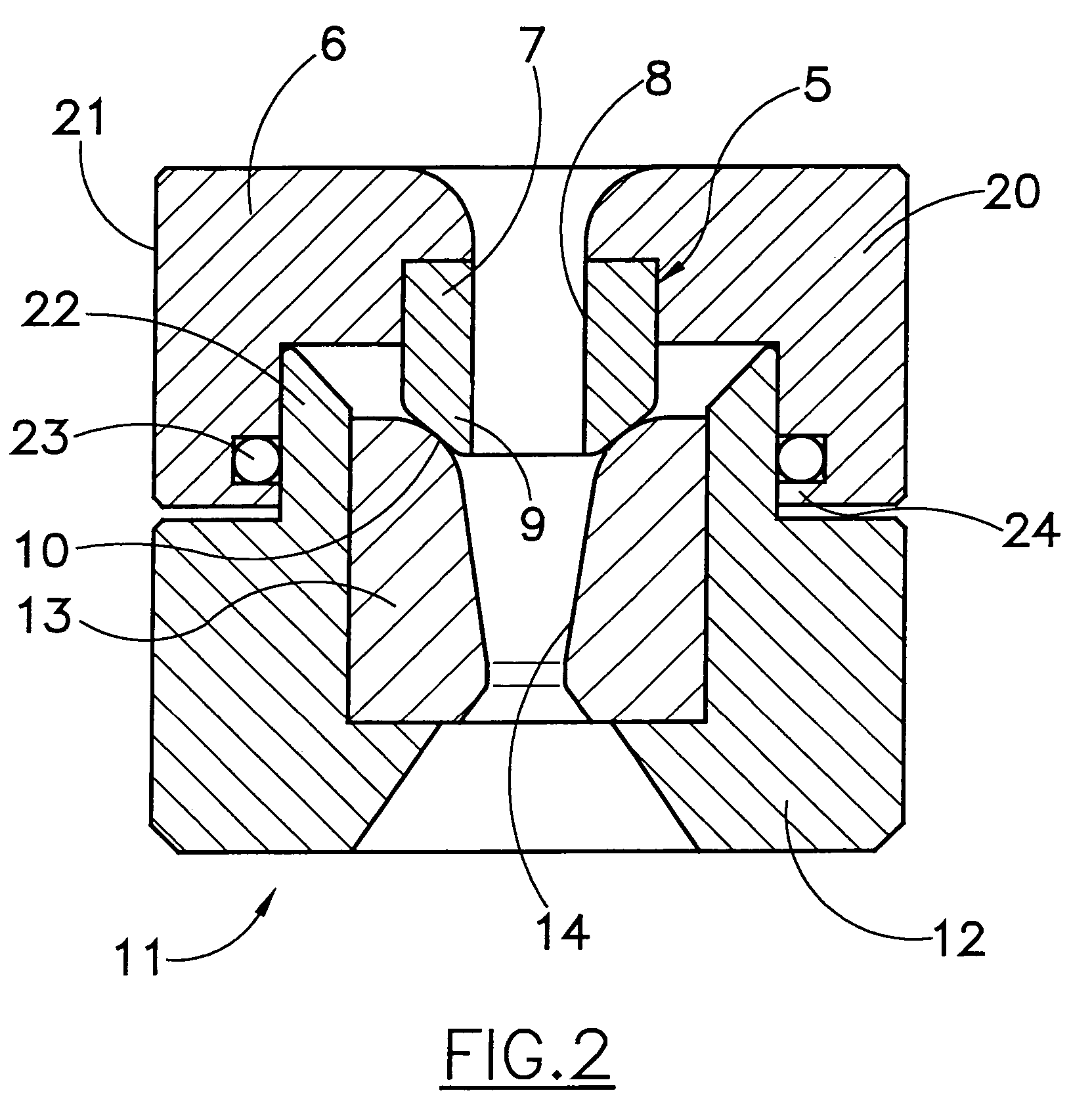
[0013]With reference to FIG. 1, the equipment comprises an external body 1 fitted internally with a tank 2 containing calcium or sodium-based stearates or other lubrication material. Said tank 2 presents at one side end an input hole 3 for the passage of a metal wire 4 (steel, copper, aluminium, etc.) that has to be drawn. The diameter of the hole 3 is greater than the section of the metal wire 4. The tank 2 is also fitted at the other side end with a sleeve 5 contained in a casing 6, generally made of steel, and comprising a circular-sectioned body 7, generally made of tungsten carbide commonly called hard metal or widia, fitted with a hole which in its central part 8 has a cylindrical conformation with a diameterjust greater than that of the wire 4 in input.

[0014]As can be seen better in FIG. 2, said circular-sectioned body 7 has in one of its ends a truncated cone extension 9 that juts out of the casing 6 in the central part of the casing. Said casing 6 has in addition a lower an...


PUM


Abstract

Equipment for cold-drawing a metal wire. The equipment includes a succession of a sleeve with a cylindrical hole and a threading die with a conical hole. The sleeve is inserted into a support and terminates with an extension inserted into the conical hole of the threading die. The support has a first annular projection and the threading die has a second annular projection coupled to the first projection so as to keep the sleeve and the threading die in position.

Description

[0001]This is a nationalization of PCT / EP03 / 11172 filed Oct. 6, 2003 and published in English.FIELD OF THE INVENTION[0002]The present invention refers to equipment for cold-drawing a metal wire.BACKGROUND OF THE INVENTION[0003]Drawing, that is the reduction of the section of a wire or other metal article through threading dies, is obtained by pulling the material through the threading die by means of drawbench machines.[0004]A commonly used technique specially for metal wires with round section enables the drawing of metal wire to be obtained by means of successive section reductions due to the wire passing through threading dies positioned one after the other and contained, together with a tank containing lubricant for the wire, in a single equipment for wiredrawing. Lubrication in this equipment is achieved by means of interposition of lubricant between the metal wire and the threading die because of both the motion of the wire towards the threading die and the spatial geometric p...

Claims


Application Information

Patent Timeline
IPC IPC(8): B21C3/14
CPCB21C3/14
Inventor VASSENA, GIUSEPPE
Owner VASSENA FILIERE
Why Eureka
Try Eureka