
Method of fastening adherend to coating object, and fastened composite

a technology of adhesive and coating object, which is applied in the direction of friction lining, friction elements, other domestic articles, etc., can solve the problems of increasing the cost of adhesive and other materials, the cost of equipment for this step, and the drop in productivity, so as to prevent the increase in the cost of adhesive and other materials, the effect of improving corrosion resistance and simple constitution

Active Publication Date: 2015-06-18
DENSO CORP
View PDF1 Cites 1 Cited by
  • Summary
  • Abstract
  • Description
  • Claims
  • Application Information

AI Technical Summary

Benefits of technology

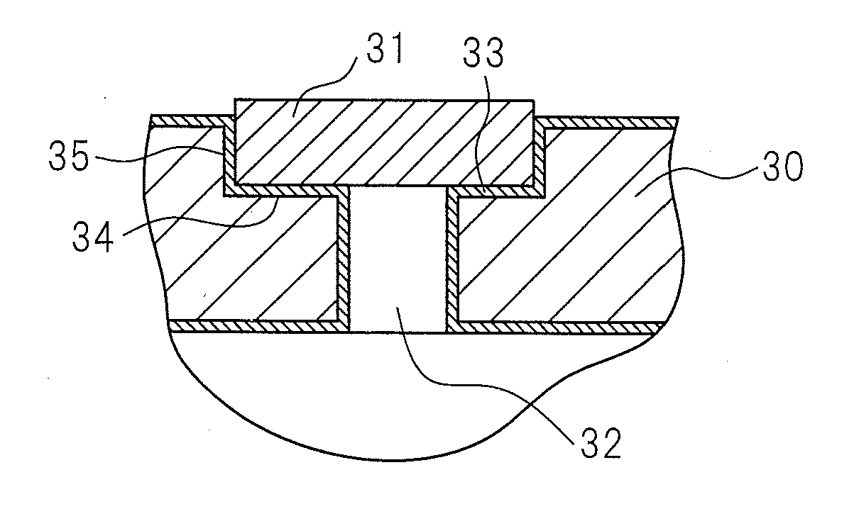
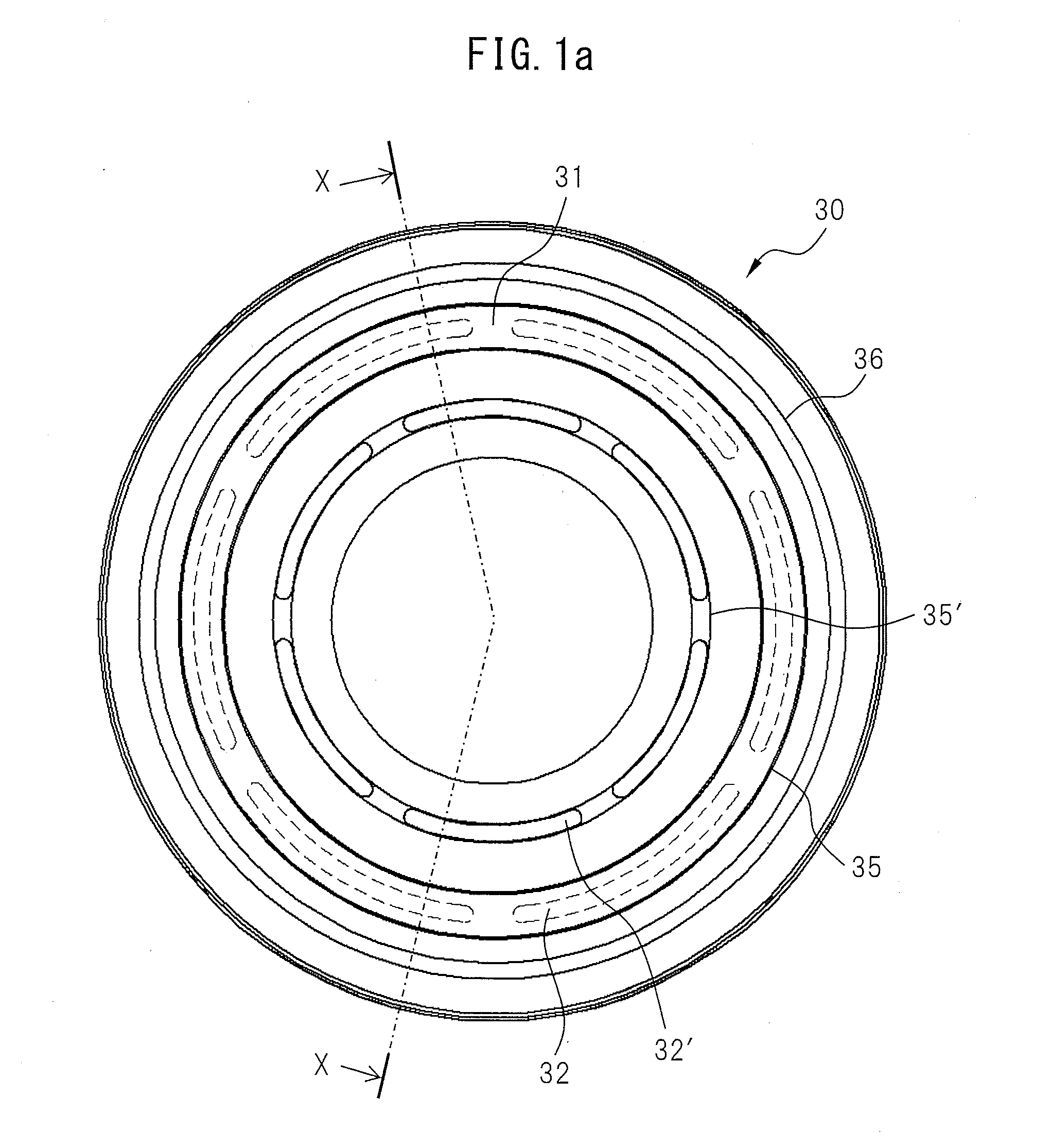
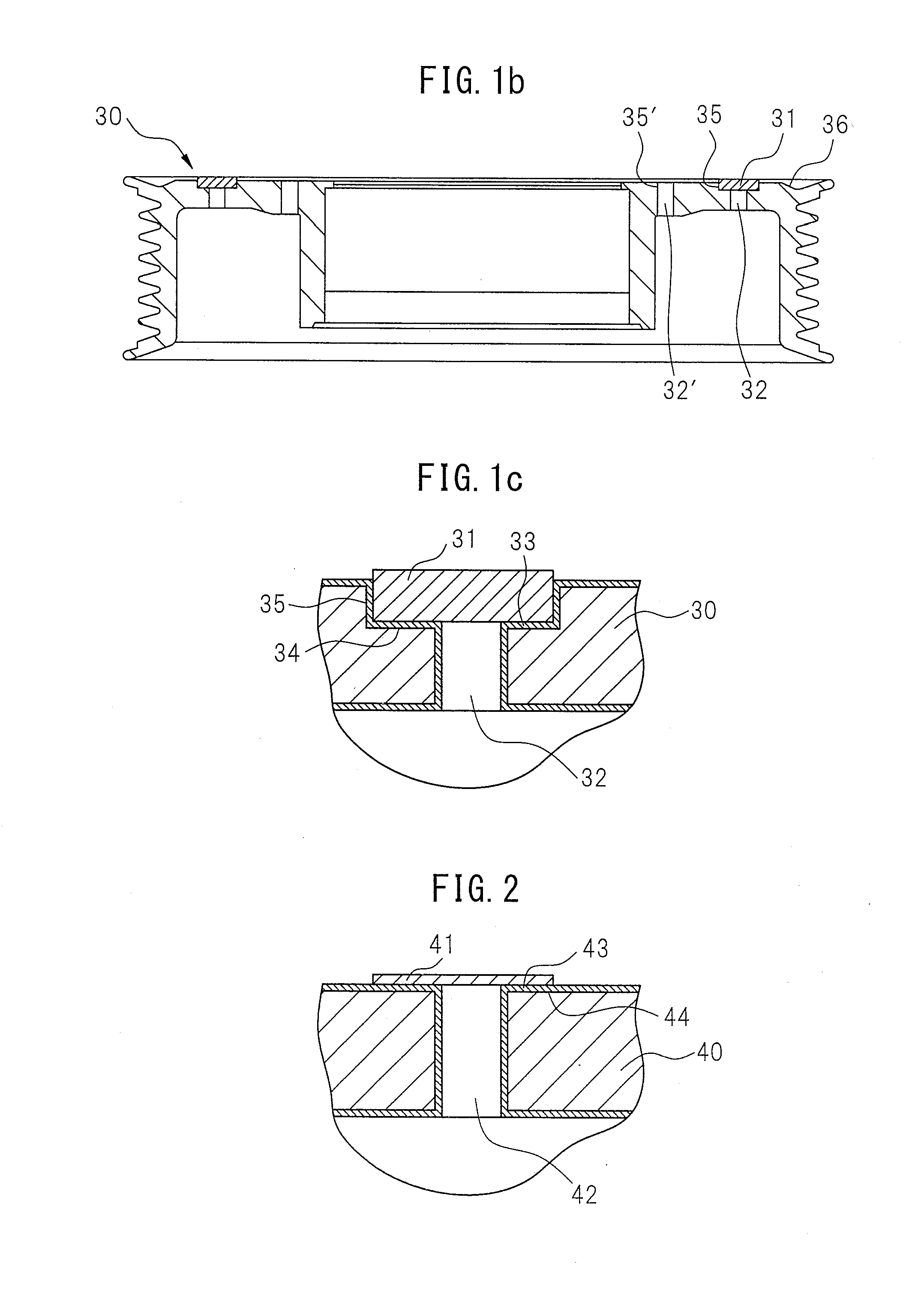
The present invention aims to provide a method for fastening two objects together using a simple composition, without the need for an adhesive layer. The method involves coating a paint film with a thermosetting resin and then pressing it onto a friction material. The paint film then cures, creating a strong bond between the two objects. This method eliminates the need for a separate adhesive layer and reduces costs associated with labor, materials, and equipment. Additionally, the invention provides a fastened composite with a simple structure, allowing for easy and quick fastening.

Problems solved by technology

In the above way, coating an adhesive for the purpose of adhering the surface of a paint film, obtained after a paint containing a thermosetting resin etc., being coated and cured in advance, and an adherend, such as a friction material or the like, to thereby adhere the two required the step of specially coating an adhesive for adhesion, and had the problems of an increase in the costs of the adhesive and other materials, the labor and time required for this step, and the cost of the equipment for it and a drop in productivity due to the load in management of the coating of adhesive etc., and further had the problem that the required adhesive strength was difficult to obtain, merely with coating one part with a resin-based paint having adhesiveness, assembling the coated part with another part in an abutting state, and then baking them.

Method used


Image

  • Method of fastening adherend to coating object, and fastened composite
  • Method of fastening adherend to coating object, and fastened composite
  • Method of fastening adherend to coating object, and fastened composite

Examples


example 1

[0071]As shown in FIGS. 3(a) to (c), a coated film 53′ with a substantially uniform thickness of 50 μm was formed by supplying a powder state thermosetting resin-containing paint 56 with an average particle size of 30 to 40 μm, containing a thermosetting resin, i.e., an epoxy resin, (60.0 wt %), a curing agent (2.0 wt %), an additive (2.0 wt %) and a pigment (36.0 wt %) from an electrostatic powder spraying type feeding means 55 on the entire surface of a rotor 50 of a magnetic clutch, i.e., the coating object, mainly comprised of iron, and provided with a ring-shaped groove shape part 57 having a 81.7 mm inside diameter, 95.4 mm outside diameter, 6.9 mm width and 1.7 mm depth, on which a ring-shaped friction member 51 (inside diameter 81.9 mm, outside diameter 95.3 mm, width 6.7 mm and thickness 2.0 mm) of a porous composite material, i.e., the adherend including a friction material, comprised mainly of a fiber base material should be fastened; and powder-coating by a frictional ch...

example 2

[0074]As shown in FIGS. 4(a) to (c), a coated film 63′ with a substantially uniform thickness of 50 μm was formed by supplying a powder state thermosetting resin-containing paint 66 with an average particle size of 30 to 40 μm, containing a thermosetting resin, i.e., an epoxy resin, (60.0 wt %), a curing agent (2.0 wt %), an additive (2.0 wt %) and a pigment (36.0 wt %) from an electrostatic powder spraying type feeding means 65 on the entire surface of a rotor 60 of a magnetic clutch, i.e., the coating object, mainly comprised of iron, and provided with a ring-shaped groove shape part 67 having a 81.7 mm inside diameter, 95.4 mm outside diameter, 6.9 mm width and 1.7 mm depth, on which a ring-shaped friction member 61 (inside diameter 81.9 mm, outside diameter 95.3 mm, width 6.7 mm and thickness 2.0 mm) of a porous composite material, i.e., the adherend including a friction material, comprised mainly of a fiber base material should be fastened; and powder-coating by a frictional ch...

example 3

[0077]As shown in FIG. 3(a), a coated film 53′ with a substantially uniform thickness of 50 μm is formed by supplying a powder state active energy ray-curing resin-containing paint 56 with an average particle size of 30 to 40 μm, containing an active energy ray-curing resin “CYCLOMER P (ACA)Z-251” (60.0 wt %) from Daicel Chemical Industries, Ltd., i.e., a (meth)acrylic polymer in the side chain of which a photopolymerizable unsaturated group has been introduced by reacting an epoxy group of 3,4-epoxy cyclohexenyl methyl acrylate with a part of carboxyl groups of (meth)acrylic acid-(meth)acrylic acid ester copolymer, a photopolymerization initiator (2.0 wt %), an additive (2.0 wt %) and a pigment (36.0 wt %) from an electrostatic powder spraying type feeding means 55 on the entire surface of a rotor 50 of a magnetic clutch, i.e., the coating object, mainly comprised of iron, and provided with a ring-shaped groove shape part 57 having a 81.7 mm inside diameter, 95.4 mm outside diamete...


PUM

PropertyMeasurementUnit
particle size distributionaaaaaaaaaa
particle sizeaaaaaaaaaa

Abstract

Provided are a fastened composite and a method of fastening an adherend, which includes a friction material, to a coating object, comprising; forming on at least a part of a surface of the coating object a coated film with a curable resin-containing paint; and fastening the adherend to the surface of the coating object, by subjecting heating and / or irradiation of an active energy ray to the coated film, while making the adherend closely contact the coated film to press it by a predetermined pressure, to cure the coated film.

Description

TECHNICAL FIELD[0001]The present invention relates to a method of fastening an adherend to a coating object, and a fastened composite which is obtained by that method. More particularly, it relates to an improved method of fastening a friction material in a friction type power transmission system, power absorption system, etc., and a fastened composite which is obtained by this method.BACKGROUND ART[0002]For example, in a clutch, brake, automatic transmission, limited slip differential, hoist, synchronizer, torque converter, torque transmission system, or other friction type power transmission system or power absorption system etc., in general, one or more sets of co-actuating members are provided together with a friction material. One of the co-actuating members is driven or braked by the other.[0003]Further, to transmit rotational drive force to a compressor for an air-conditioner which is mounted in an automobile, or to disconnect it, in the past, a magnetic clutch including a me...

Claims


Application Information

Patent Timeline
Patent Type & Authority Applications(United States)
IPC IPC(8): F16D69/04B32B37/18B32B38/00B32B7/12
CPCF16D69/04B32B7/12F16D2069/0475B32B38/0008B32B2475/00B32B37/182F16D27/112F16D2250/0046Y10T428/31515C09J5/06C09D5/08B32B15/04
Inventor KADO, KUNIHIROMIZUTORI, KAZUNORITABUCHI, YASUOSAKURABA, SHIGEYOSHI
Owner DENSO CORP
Learn More