Supercharge Your Innovation With Domain-Expert AI Agents!

Pierce cam

a pierce cam and pierce technology, applied in the field of pierce cams, can solve the problems of large sized, difficult mounting, high cost, etc., and achieve the effect of saving space, reducing cost, and being easy to moun

Inactive Publication Date: 2007-11-06
UMIX
View PDF13 Cites 0 Cited by
  • Summary
  • Abstract
  • Description
  • Claims
  • Application Information

AI Technical Summary

Benefits of technology

"The present invention provides a compact, space-saving, easily mounted, cost-effective, and even mountable on a sloped surface pierce cam. The cam includes a pierce punch, a detachable body, a stripper, a rotating arm, and a driver. The cam can be easily mounted on a press machine and used for piercing materials. The technical effects of the invention include compact design, space saving, easy mounting, cost reduction, and versatility in mounting on sloped surfaces. Additionally, the invention allows for the ordering of pierce punch and required accessories from a single source."

Problems solved by technology

As mentioned above, the conventional pierce cam is large-scaled, requires a lot of space, is hard to be mounted, is expensive, and is hard to be mounted to a slope surface.

Method used


Image

  • Pierce cam
  • Pierce cam
  • Pierce cam

Examples


Embodiment Construction

[0029]A detailed description of the present invention will be given below on the basis of a specific embodiment shown in the accompanying drawings.

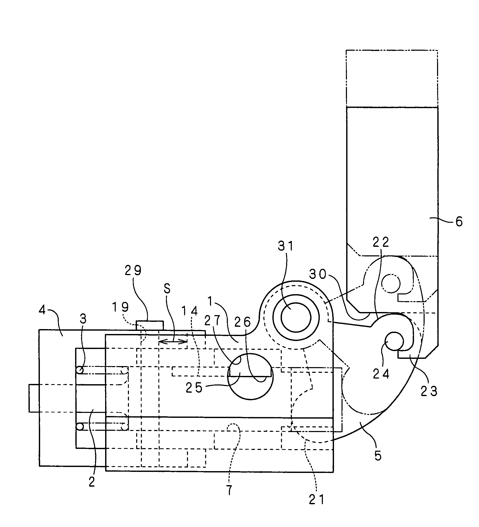
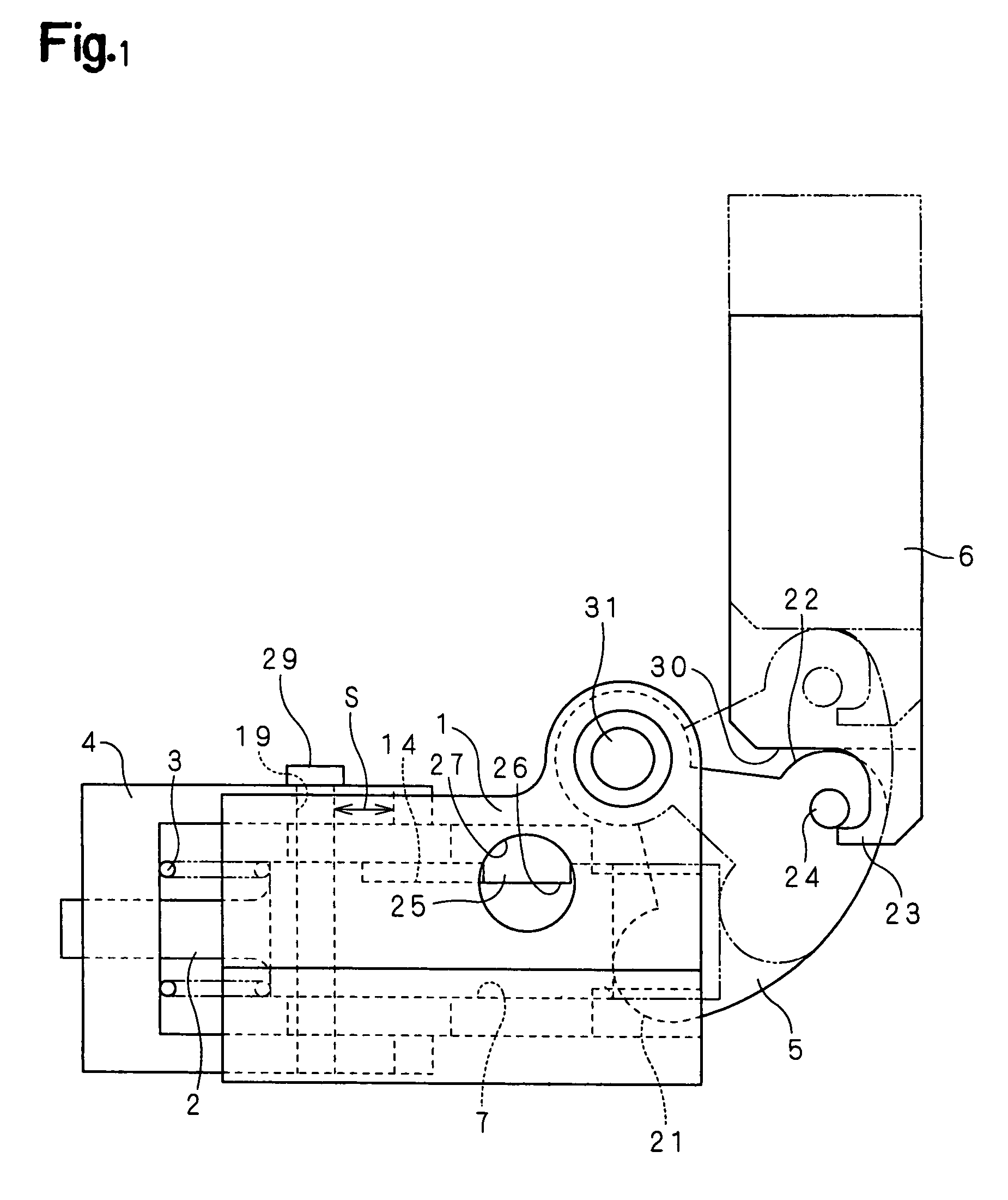
[0030]FIG. 1 is a front elevational view of a pierce cam in accordance with a specific embodiment of the present invention, and FIG. 2 is a plan view excluding a driver.

[0031]A pierce punch 2 is detachably provided in a body 1, a stripper 4 energized by a coil spring 3 is slidably provided in the body 1, an oscillating arm 5 is swingably pivoted to the body 1, a lower portion of the oscillating arm 5 is brought into contact with a rear end surface of the pierce punch 2, and a driver 6 provided in a trailing manner in an upper die transfers a downward moving force of a press machine to the oscillating arm 5, and hooks the rotating arm 5 at the time of moving upward.

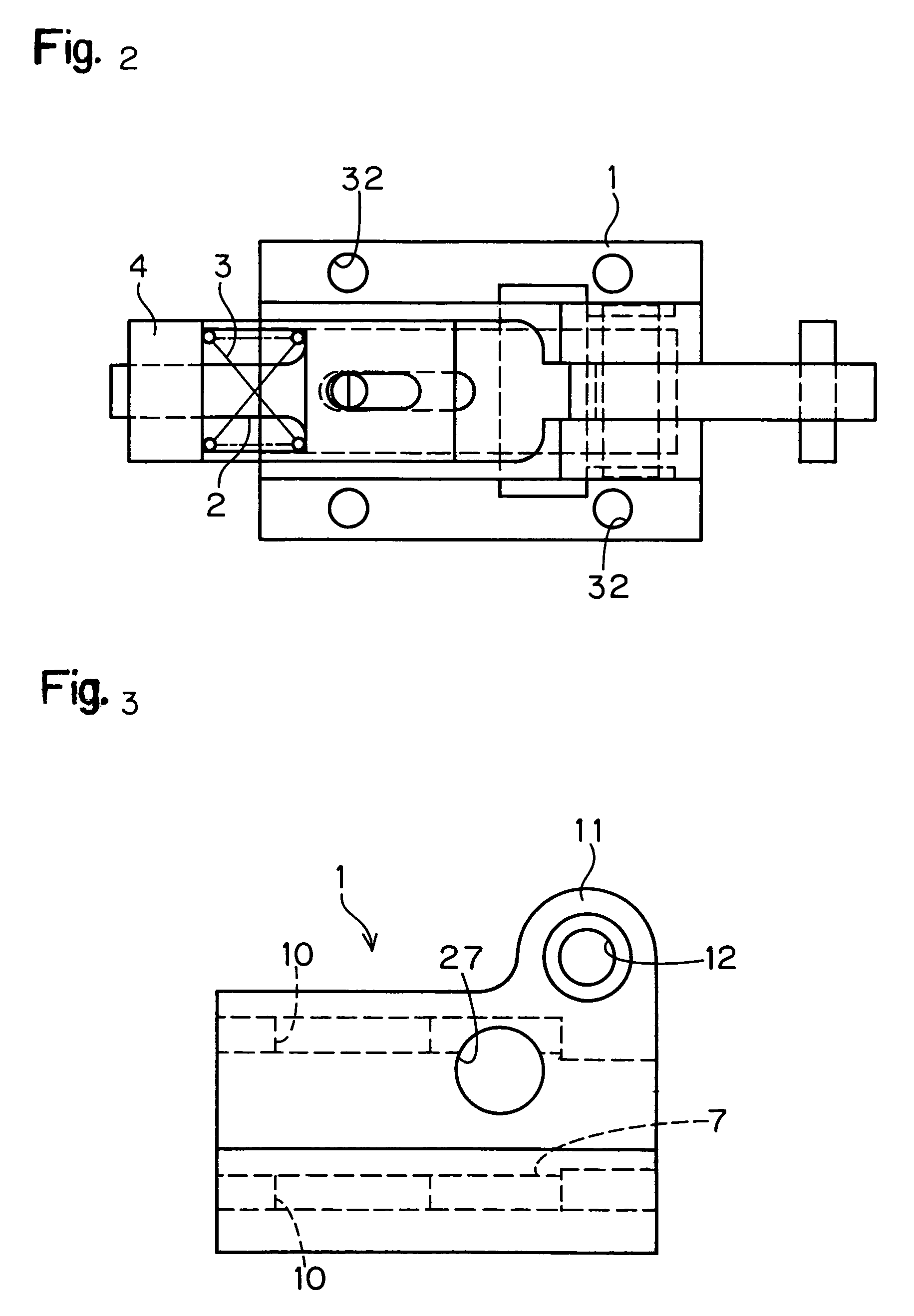
[0032]Details of the body 1 will be shown in FIGS. 3 to 5. FIG. 3 is a front elevational view of the body 1, FIG. 4 is a side elevational view of the same and FIG. 5 is a plan v...


PUM

PropertyMeasurementUnit
hole diameteraaaaaaaaaa
forceaaaaaaaaaa
stroke lengthaaaaaaaaaa

Abstract

A pierce cam is compact, can save space, can be easily mounted, can reduce cost, can even be mounted to a sloped surface, and a pierce punch and required accessories can be ordered in bulk from a single source. A pierce cam includes a pierce punch, a body which is detachably provided with the pierce punch, a stripper which is fitted to the pierce punch inward of a leading end portion of the pierce punch and is biased by a coil spring in a direction away from the body, a rotating arm which is swingably mounted on the body and is movable into contact with a rear end surface of the pierce punch, and a driver which transfers a descending force of a press machine to the rotating arm, and hooks and ascends the rotating arm at the time of moving upward.

Description

[0001]This Non-provisional application claims priority under 35 U.S.C. § 119(a) on Patent Application No(s). 2003-344676 filed in Japan on Oct. 2, 2003, the entire contents of which are hereby incorporated by reference.BACKGROUND OF THE INVENTION[0002]1. Field of the Invention[0003]The present invention relates to a pierce cam, and more particularly to a standardized piece cam.[0004]2. Description of Background Art[0005]A conventional pierce cam is constituted, as shown in FIG. 16, by a pierce punch 101, a punch plate 102 which holds the pierce punch 101, a stripper 103 which presses a work W before piercing by the pierce punch 101 and takes away the pierce punch 101 from the work W after piercing, a cushion rubber (there is a case of a coil spring) 104 which presses the stripper 103, a passive cam 105 which mounts the punch plate 102 thereto and moves backward and forward toward the work W, an actuating cam 106 which moves forward the passive cam 105, a base plate block 107 which s...

Claims


Application Information

Patent Timeline
Patent Type & Authority Patents(United States)
IPC IPC(8): B26D5/00B26F1/14B21D28/34B21D28/00B21D28/32B21D37/08
CPCB21D28/32B21D28/002Y10T83/8727Y10T83/2166Y10T83/8828Y10T83/9423Y10T83/8841
Inventor KITAMURA, NORITOSHI
Owner UMIX
Features
  • R&D
  • Intellectual Property
  • Life Sciences
  • Materials
  • Tech Scout
  • Unparalleled Data Quality
  • Higher Quality Content
  • 60% Fewer Hallucinations
Learn More