
Leaf spring assembly with retaining device

a technology of retaining device and leaf spring, which is applied in the direction of spring/damper design characteristics, resilient suspension, vehicle springs, etc., can solve the problems of no method of containing the fractured pieces within the vehicle, leaf spring system does not incorporate deflection limitation device to protect the leaf spring from potential failure, and the failure of the leaf spring system. to prevent the effect of subsequent damage to the publi

Active Publication Date: 2007-11-06
IMT STANDENS
View PDF10 Cites 0 Cited by
  • Summary
  • Abstract
  • Description
  • Claims
  • Application Information

AI Technical Summary

Benefits of technology

[0010]The retaining device of the present invention retains broken parts of a failed leaf spring with the assembly. Keeping such parts with a vehicle using the assembly prevents subsequent damage to the public by keeping the parts out of the general roadway. A leaf spring typically fails in the area near the leaf fastener, so by attaching the retaining device on opposite sides of the fastener, a fractured piece of a leaf spring stays secured to the other springs. The retaining device can be added to existing types of leaf spring assemblies without design changes or excessive modifications.

Problems solved by technology

Typically, these leaf spring systems do not incorporate deflection limitation devices to protect the leaf springs from potential failure precipitated by overloading.
If overload does occur the leaf spring may fracture and there is no method of containing the fractured pieces within the vehicle.
Subsequently, if a spring fails, the broken pieces generally dislodge from the vehicle and represent a danger to the public.

Method used


Image

  • Leaf spring assembly with retaining device
  • Leaf spring assembly with retaining device
  • Leaf spring assembly with retaining device

Examples


Embodiment Construction

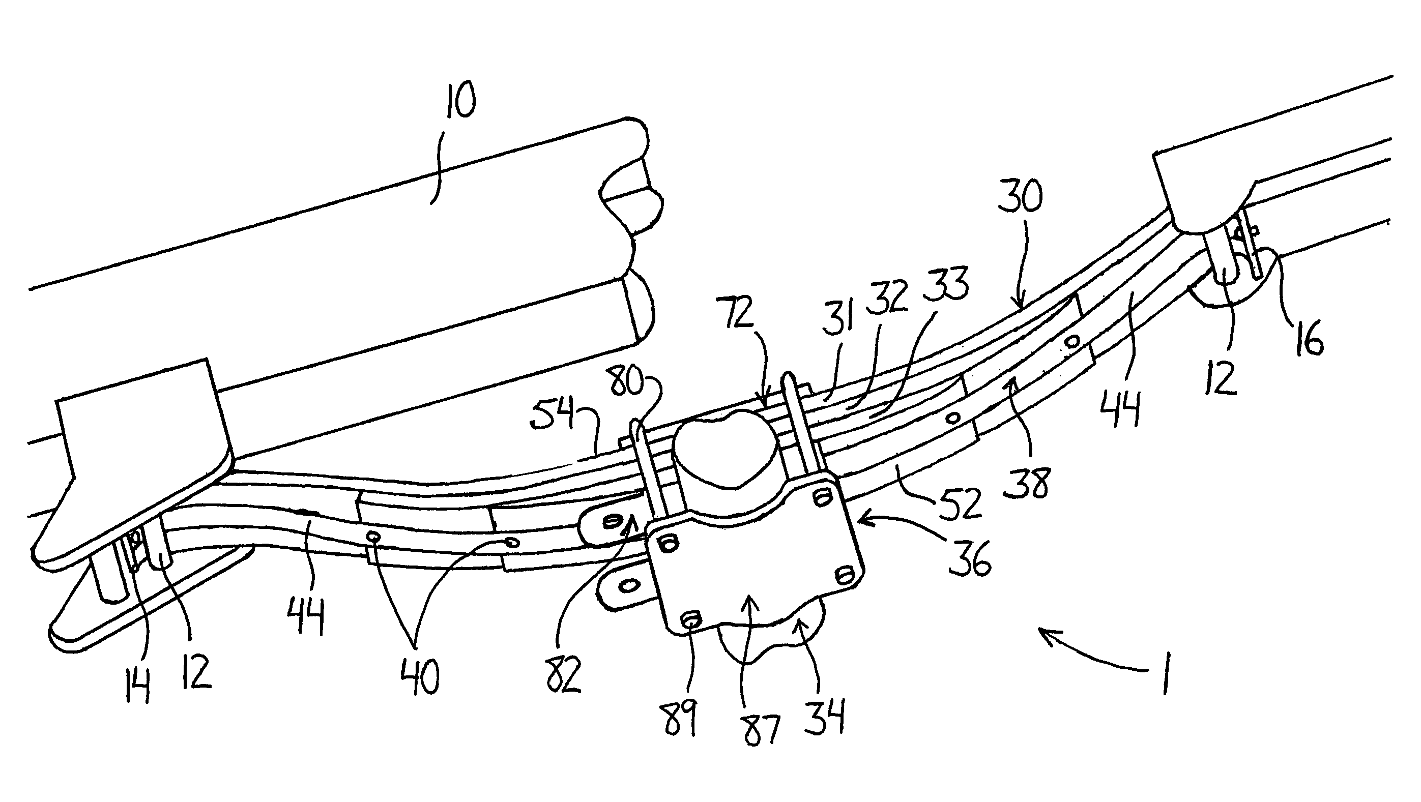
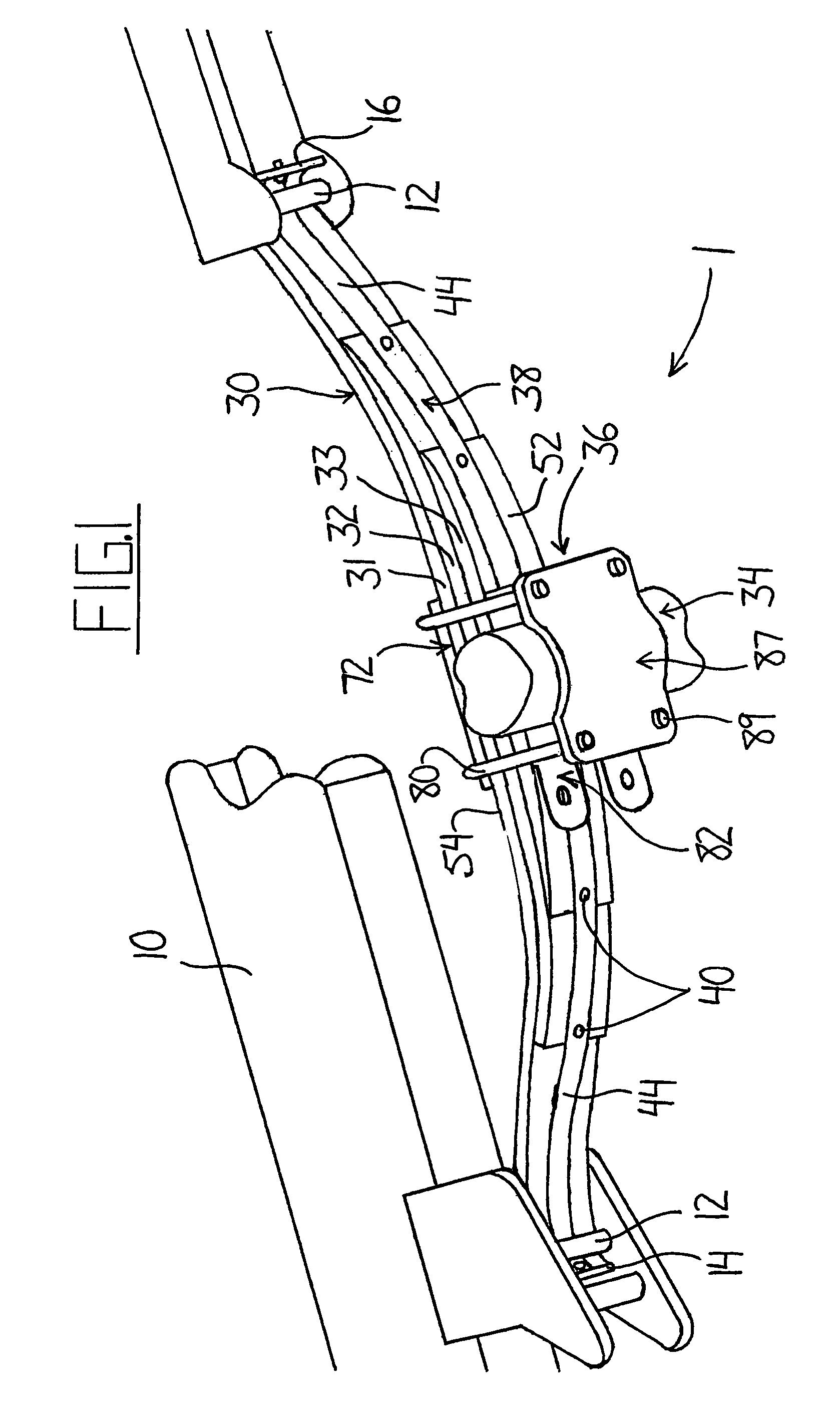
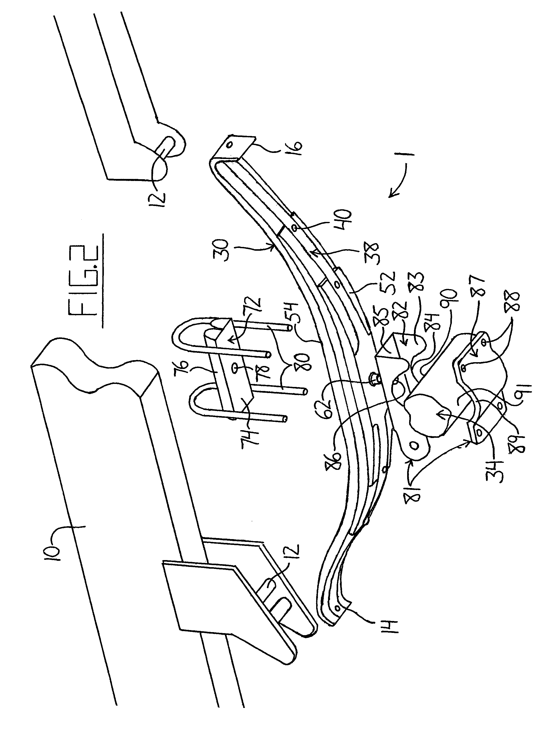
[0033]FIG. 1 shows a leaf spring assembly 1 according to one embodiment of the present invention. As typically found in four spring suspension systems designed to distribute vehicle weight between axles, a leaf spring assembly 1 is mounted on the vehicle frame 10 by spring hangers 12. The leaf spring assembly 1 features a stack 30 of progressively shorter leaf springs 31 to 33 that are connected to an axle 34 by means of a mounting coupling 36. The top spring 31 is the longest and has ends 14 and 16 adapted to engage the hangers 12 by means of downwardly curved portions. The spring leaf assembly 1 of the present invention features the addition of a safety strap 38 extending along the bottom of the stack 30 of leaf springs 31 to 33. The strap 38 acts as a retaining device and is attached to each leaf spring 31 to 33 at opposite ends by rivets 40. In this arrangement, the leaf springs 31 to 33 are connected to each other on either side of the mounting coupling 36 such that if any spri...


PUM


Abstract

A leaf spring assembly includes a safety strap extending along the bottom of a plurality of stacked leaf springs that are held in a stacked relationship by a leaf fastener. The strap is attached to each leaf spring in the stack by fasteners at opposite ends of the spring such that adjacent leaf springs are connected on each side of the fastener. In the event that any one of the springs fails between the leaf fastener and one of the ends at which the strap is attached, the broken pieces of the spring remain connected to the other springs in the stack. This prevents pieces from breaking free of the assembly and creating road hazards in the event of spring failure.

Description

[0001]This invention relates generally to leaf spring suspension assemblies, and more particularly to a way to retain fractured pieces of a leaf spring on a leaf spring assembly in the event of leaf spring failure.BACKGROUND OF THE INVENTION[0002]Leaf spring assemblies are conventionally used for suspending one component relative to another. Vehicle suspension is one example of an application using such assemblies. However a leaf spring assembly can be used in many different situations and the present invention is applicable to any of these and is not intended to be limited to vehicle suspensions.[0003]A four spring suspension system used extensively in the highway transportation trailer industry features four leaf spring assemblies. Each of these leaf spring assemblies includes a plurality of individual leaf springs of varying lengths stacked one atop the other and connected together at approximately a center point along their length. The longest leaf spring has its ends shaped to ...

Claims


Application Information

Patent Timeline
Patent Type & Authority Patents(United States)
IPC IPC(8): B60G11/02F16F1/18
CPCB60G9/003B60G11/04F16F1/26B60G2200/31F16F2230/24B60G2204/121B60G2204/4306B60G2202/112
Inventor SVENDSEN, MELVINSTOESZ, DONALDFENG, SIMONJARRY, LUCBOLL, MARTY
Owner IMT STANDENS
Learn More