Micromachined spinneret

a micro-machined, spinneret technology, applied can solve the problems of many problems which have not yet been solved in the field of spinnerets

Active Publication Date: 2007-11-06
NAT TECH & ENG SOLUTIONS OF SANDIA LLC
View PDF12 Cites 8 Cited by
  • Summary
  • Abstract
  • Description
  • Claims
  • Application Information

AI Technical Summary

Benefits of technology

[0012]A heating element can be formed proximate to each orifice in the first array of orifices, with the heating element comprising, for example, polycrystalline silicon. Alternately, or in conjunction with the heating element, one or more pairs of spaced-apart electrodes can be formed proximate to each orifice in the first array of orifices. Each electrode can comprise polycrystalline silicon or metal.
[0013]Each orifice in the first array of orifices can have a width of 100 microns or less; and each orifice in the second array of orifices can have an

Problems solved by technology

The formation of artificial silk fibers on a large scal

Method used


Image

  • Micromachined spinneret
  • Micromachined spinneret
  • Micromachined spinneret

Examples


Embodiment Construction

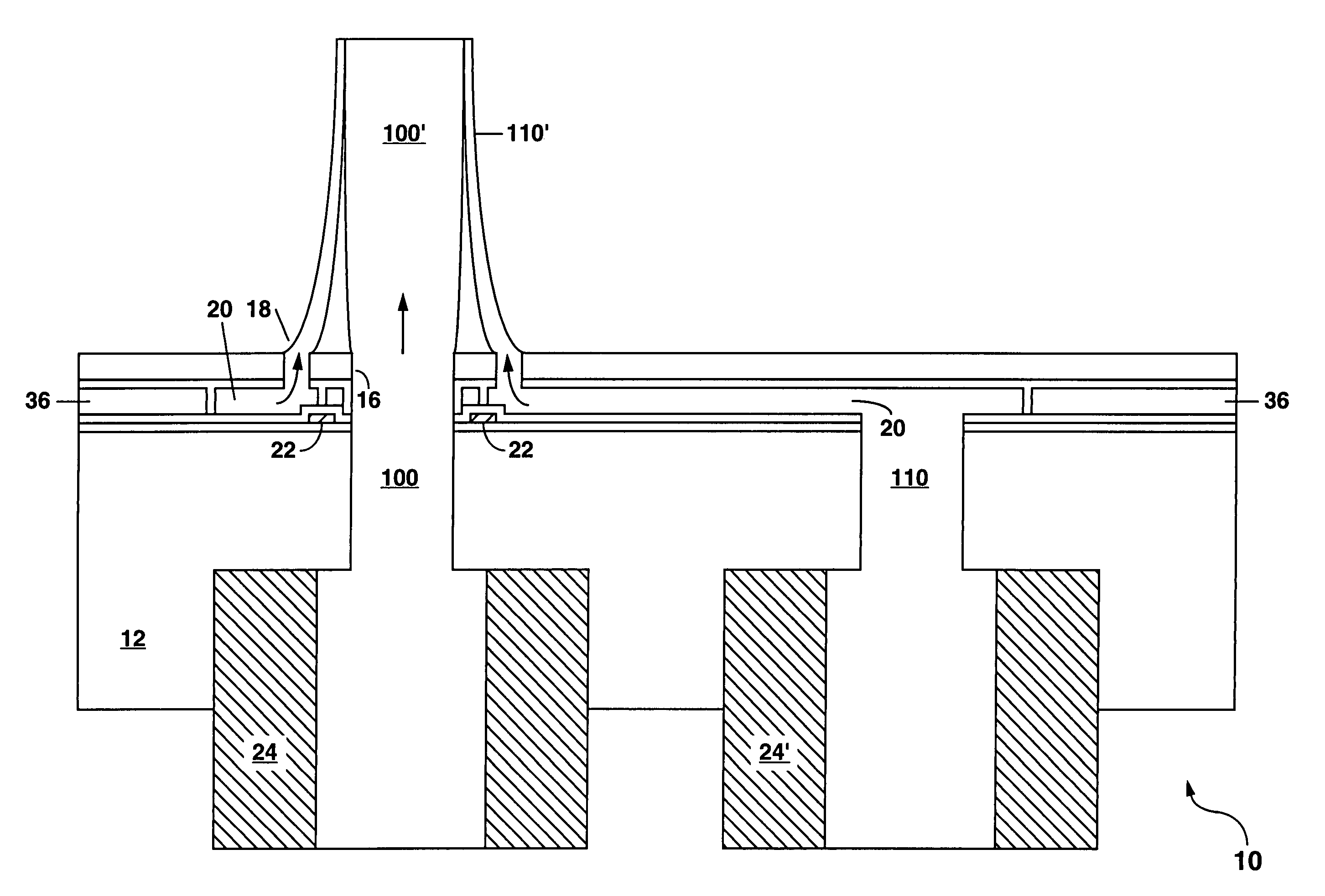
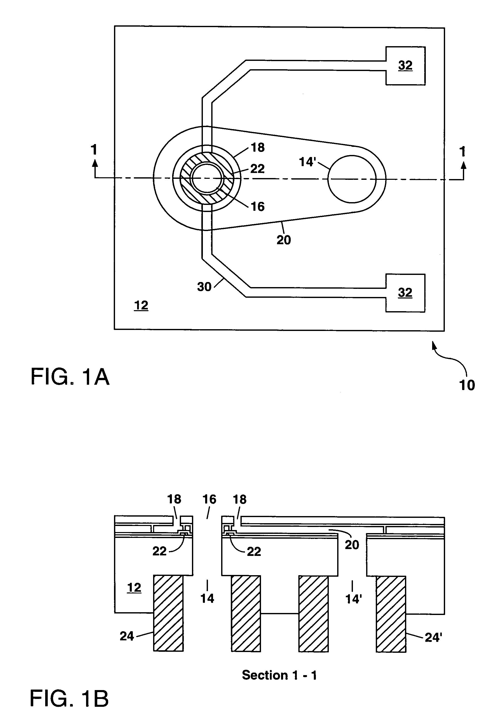
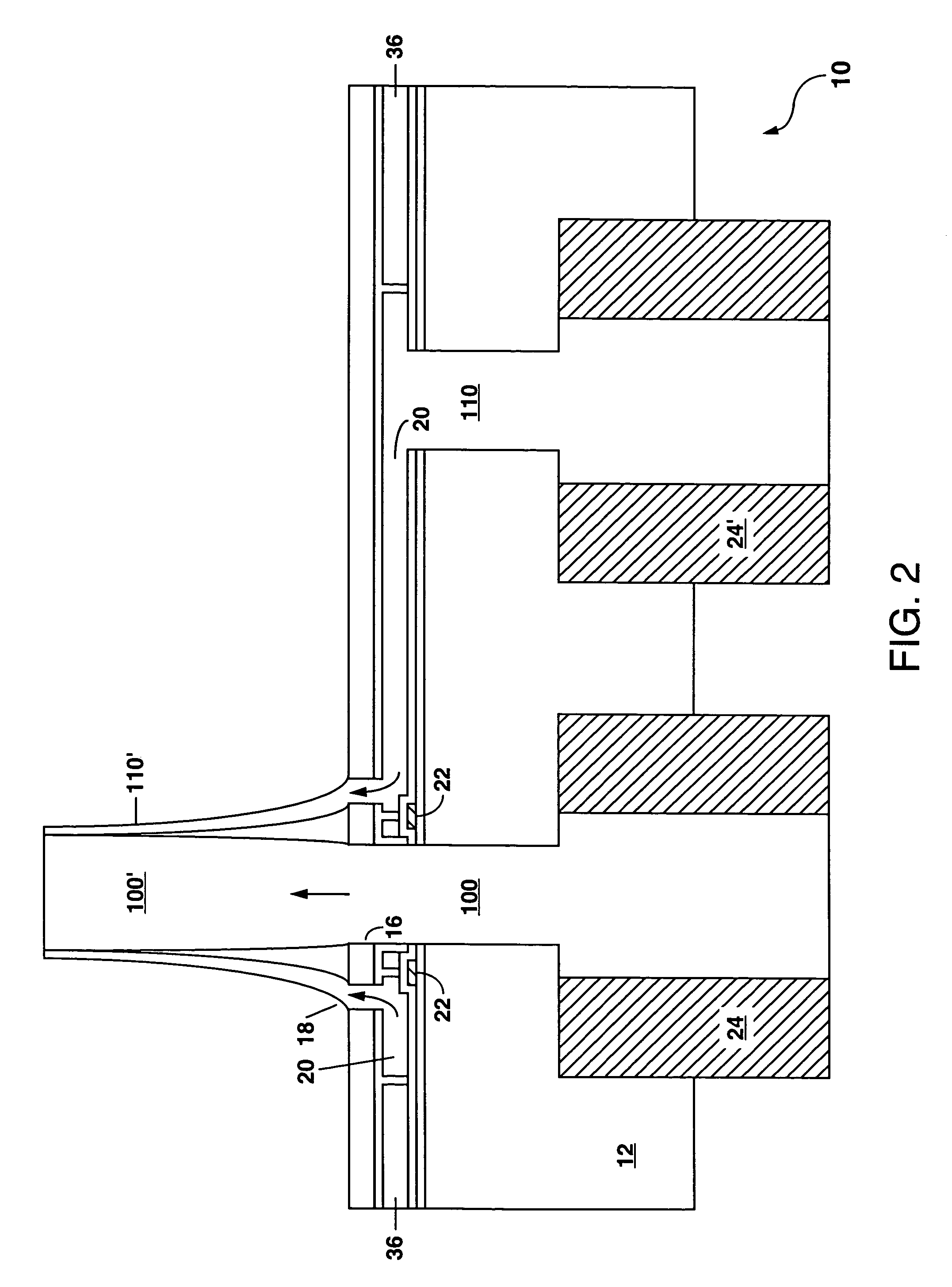
[0026]Referring to FIG. 1, there is shown a schematic cross-section view of a first example of a micromachined spinneret 10 according to the present invention. The spinneret 10 comprises a substrate 12 having a pair of fluid feed ports 14 and 14′ formed through the substrate 12 from one major surface thereof to the other major surface thereof. The term “fluid” as used herein is intended to include extrudable materials and co-extrudable materials in addition to liquids and gases. A circular orifice 16 is formed on an upper major surface of the substrate 12 from a plurality of layers of deposited and patterned silicon nitride and polycrystalline silicon. The circular orifice 16 (also termed herein a first orifice) is surrounded by an annular orifice 18 (also termed herein a second orifice) which is formed from the same plurality of layers of deposited and patterned silicon nitride and polycrystalline silicon (also termed polysilicon). The annular orifice 18 is connected to fluid feed ...


PUM

PropertyMeasurementUnit
Timeaaaaaaaaaa
Widthaaaaaaaaaa
Widthaaaaaaaaaa

Abstract

A micromachined spinneret is disclosed which has one or more orifices through which a fiber-forming material can be extruded to form a fiber. Each orifice is surrounded by a concentric annular orifice which allows the fiber to be temporarily or permanently coated with a co-extrudable material. The micromachined spinneret can be formed by a combination of surface and bulk micromachining.

Description

GOVERNMENT RIGHTS[0001]This invention was made with Government support under Contract No. DE-AC04-94AL85000 awarded by the U.S. Department of Energy. The Government has certain rights in the invention.FIELD OF THE INVENTION[0002]The present invention relates in general to spinnerets for forming fibers, and in particular to a micromachined spinneret formed from a plurality of layers of polycrystalline silicon and silicon nitride deposited on a substrate and patterned by micromachining to form one or more pairs of concentric orifices therethrough. Embodiments of the micromachined spinneret can be used to form coated fibers, or a thread consisting of a plurality of fibers.BACKGROUND OF THE INVENTION[0003]Spinnerets are useful to extrude fibers of different types. Genetically modified proteins are now being developed with the goal of producing artificial silk fibers. The formation of artificial silk fibers on a large scale presents many problems which have not yet been solved.[0004]The ...

Claims


Application Information

Patent Timeline
IPC IPC(8): B29C47/08
CPCD01D4/02D01F6/68Y10S425/217
Inventor OKANDAN, MURATGALAMBOS, PAUL
Owner NAT TECH & ENG SOLUTIONS OF SANDIA LLC
Why Eureka
Try Eureka