
Inter-axle differential assembly

a technology of differential assembly and axle, which is applied in mechanical equipment, transportation and packaging, and gearing. it can solve the problems of increasing the weight of the inter-axle differential assembly, adversely affecting fuel economy, and increasing the overall component cost and assembly time. , to achieve the effect of reducing standout and being easy to assembl

Active Publication Date: 2007-11-06
ARVINMERITOR TECH
View PDF6 Cites 32 Cited by
  • Summary
  • Abstract
  • Description
  • Claims
  • Application Information

AI Technical Summary

Benefits of technology

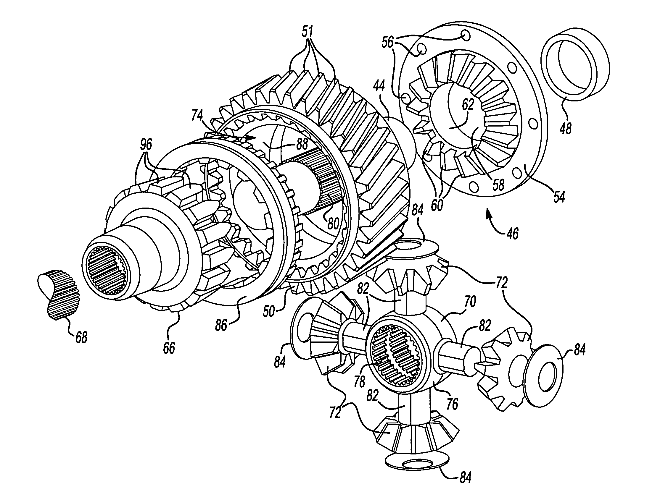
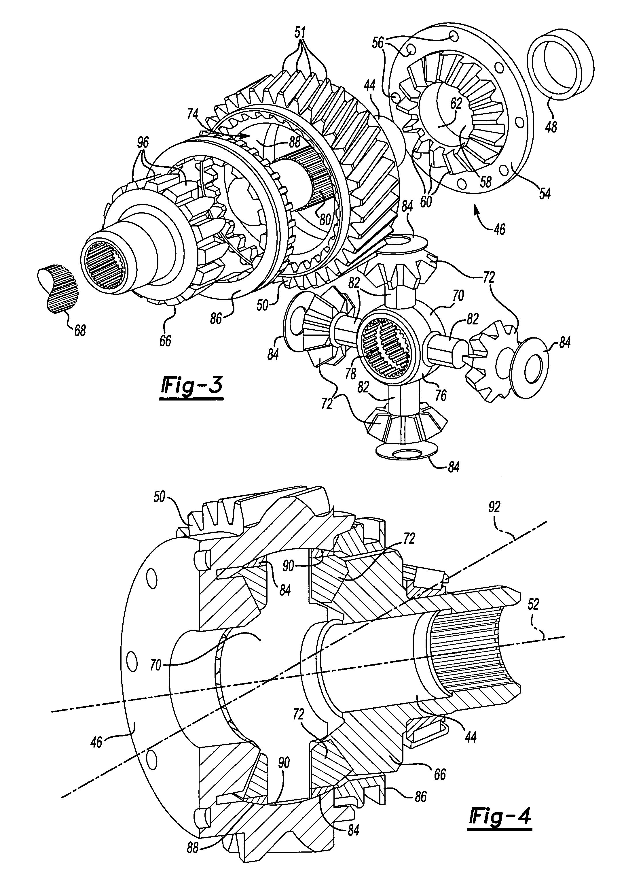
The present invention is an inter-axle differential assembly that includes a forward side gear, a rear side gear, a differential spider, and a plurality of inter-axle differential pinion gears that are in meshing engagement with the forward and rear side gears. The input shaft drives the differential spider, which drives the plurality of inter-axle differential pinion gears and the forward side gear. The forward side gear is mounted for rotation with a drive gear that provides driving input to a forward axle differential assembly. The drive gear is a helical drive gear with a center cavity that receives the plurality of inter-axle differential pinion gears. The differential spider supports the plurality of inter-axle differential pinion gears. The forward side gear is joined to one side of the helical drive gear. The inter-axle differential assembly provides a compact design that eliminates the need for an inter-axle differential housing assembly and reduces standout. It is also more lightweight and easier to assemble than prior designs.

Problems solved by technology

One disadvantage is that the inter-axle differential housing assembly significantly increases the weight of the inter-axle differential assembly.
This adversely affects fuel economy.
Further, the need for the inter-axle differential housing itself increases overall component cost and assembly time.
Another disadvantage is that this configuration can have a relatively large standout dimension.
Standout adversely affects driveline angles.
Greater driveline angles can adversely affect component wear.

Method used


Image

  • Inter-axle differential assembly
  • Inter-axle differential assembly
  • Inter-axle differential assembly

Examples


Embodiment Construction

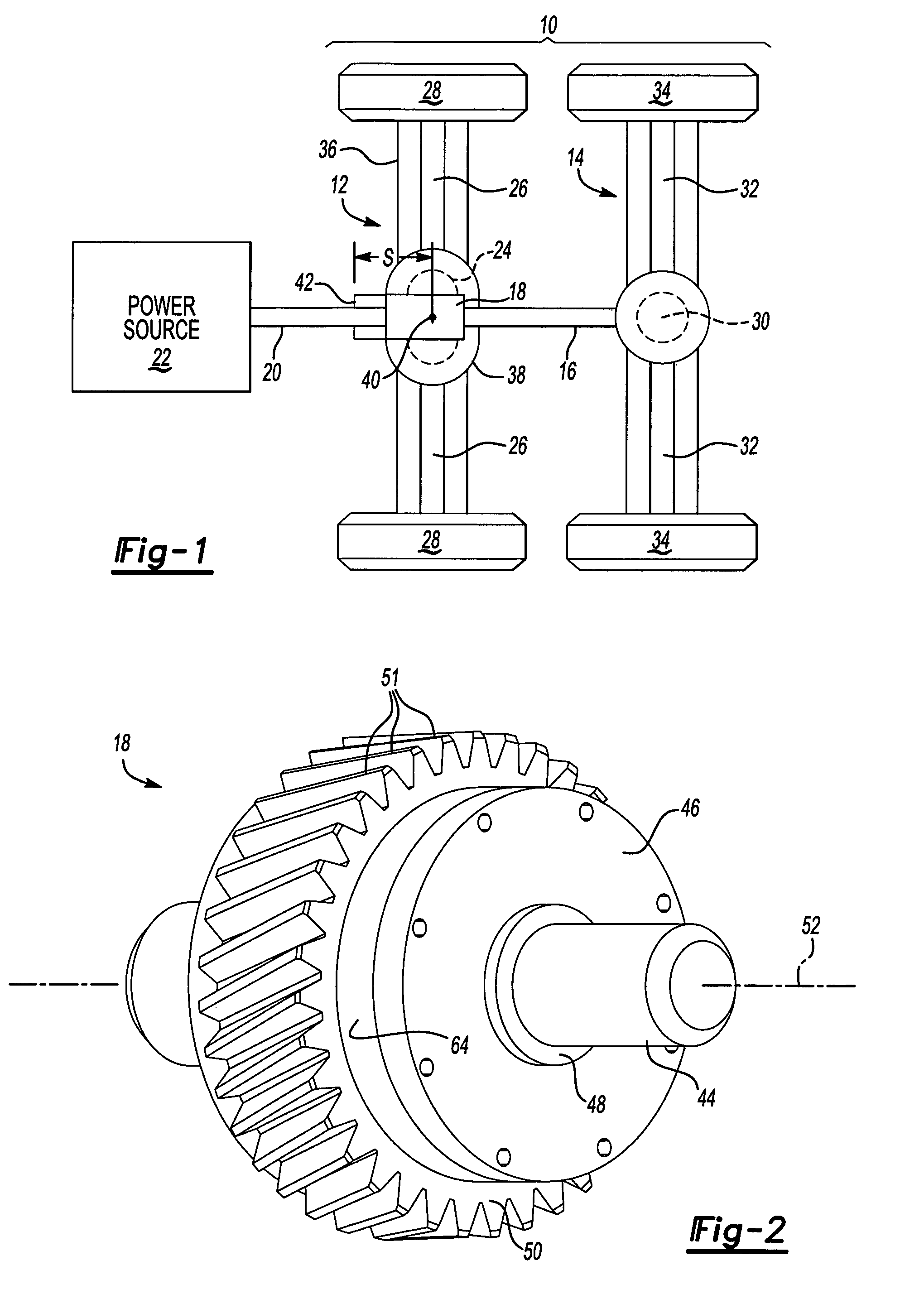
[0022]A tandem drive axle 10 is shown in FIG. 1. The tandem drive axle 10 includes a forward axle 12 and a rear axle 14 coupled to the forward axle 12 with a connecting driveshaft 16. The forward axle 12 includes an inter-axle differential gear assembly 18 that is coupled to a drive shaft 20, which is driven by a power source 22, such as an engine or electric motor, for example. Additional powertrain components such as a transmission, gearbox, clutch, or any other known powertrain components can be positioned between the power source 22 and the drive shaft 20 as known in the art. The inter-axle differential gear assembly 18 provides speed differentiation between the forward axle 12 and the rear axle 14 as is known.

[0023]The forward axle 12 includes a forward differential gear assembly 24 that is coupled to forward axle shafts 26 that drive a pair of laterally opposed forward wheel ends 28. The rear axle 14 includes a rear differential gear assembly 30 that is coupled to rear axle sh...


PUM


Abstract

An inter-axle differential assembly includes a forward side gear and a rear side gear that are supported by an input shaft. The forward and rear side gears are in meshing engagement with a plurality of inter-axle differential pinion gears that are supported on a spider. The spider is driven by the input shaft and has a plurality of legs with each leg supporting one of the plurality of inter-axle differential pinion gears. A helical drive gear is fixed for rotation with the forward side gear. The helical drive gear includes a center cavity defined by a spherical inner surface. The spider and the plurality of inter-axle differential pinion gears are positioned within the center cavity. This eliminates the need for an inter-axle differential housing assembly and reduces standout.

Description

TECHNICAL FIELD[0001]The subject invention relates to an inter-axle differential assembly including a forward side gear mounted for rotation with a helical drive gear and including a plurality of inter-axle differential pinion gears positioned in a spherical center cavity formed in the helical drive gear.BACKGROUND OF THE INVENTION[0002]A tandem drive axle is typically used to drive rear wheels on a heavy-duty commercial vehicle, such as a tractor-trailer vehicle, for example. The tandem drive axle includes a forward drive axle and a rear drive axle that are connected by an interconnecting driveshaft. The tandem drive axle includes an inter-axle differential assembly that allows speed differentiation between the forward drive axle and the rear drive axle. The inter-axle differential assembly provides speed differentiation between driving input to a forward differential gear assembly for the forward drive axle and driving input to a rear differential gear assembly for the rear drive ...

Claims


Application Information

Patent Timeline
Patent Type & Authority Patents(United States)
IPC IPC(8): F16H48/06
CPCB60K17/36F16H48/08
Inventor ALMAGUER, ADALBERTO JAIR REYES
Owner ARVINMERITOR TECH
Learn More