Artificial intervertebral disc

a technology of artificial vertebrae and discs, applied in the field of spinal implants, can solve the problems of disc degeneration, disc degeneration, and the complex system of joints being subject to varying loads and problems, and achieve the effects of reducing the risk of disc degeneration, and reducing the strength of the dis

Inactive Publication Date: 2007-11-06
AESCULAP IMPLANT SYST
View PDF82 Cites 118 Cited by
  • Summary
  • Abstract
  • Description
  • Claims
  • Application Information

AI Technical Summary

Problems solved by technology

The complex system of the joint is subjected to varying loads and problems over time, including disc degeneration due to a variety of reasons.
Disc degeneration can be attributed to aging, damage due to excessive loading, trauma, and other anatomical issues.
Facet joints of the structure can be compromised due to the same reasons, as well as due to arthritic changes.
Severe joint degeneration and failure can often cause sufficient pain to require surgical intervention.
However, since the entire spine works as a system, fusion results in complications.
A fusion alters the means by which the spine flexes, which also increases the loads on the remaining healthy discs.
In turn, it is well understood that a complication of fusion is that additional fusions may be required in the future as the other discs deteriorate due to the altered biomechanics of the spine.
A significant portion of the prior art addresses the issues of intervertebral motion but do not address anatomical loading considerations.
The current state of prior art artificial intervertebral discs are associated with various problems.
For example, a number of implants constructed from polymers are of insufficient strength to work effectively in the higher loading areas, such as the lumbar spine.
Implants constructed with ball and socket joints severely restrict or eliminate shock cushioning effect of a normal disc.
This implant can provide motion, but biomechanically, the ball and socket joint negatively affects other healthy discs of the spine.
The result can be long-term problems at other levels of the spine, as seen with the current treatment of fusion.
Polyethylene as a bearing surface is problematic in large joint replacement due to the wear properties of the material.
Since artificial discs are intended to be implanted over long periods of time, such wear can be highly damaging to surrounding tissue and bone.

Method used


Image

  • Artificial intervertebral disc
  • Artificial intervertebral disc
  • Artificial intervertebral disc

Examples


Embodiment Construction

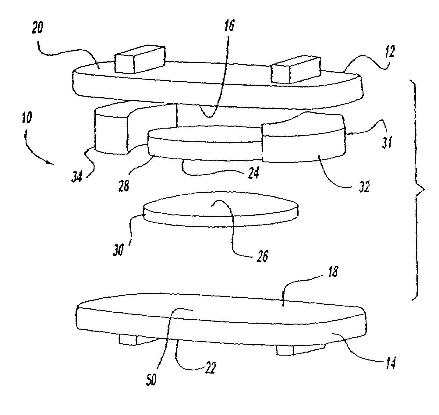
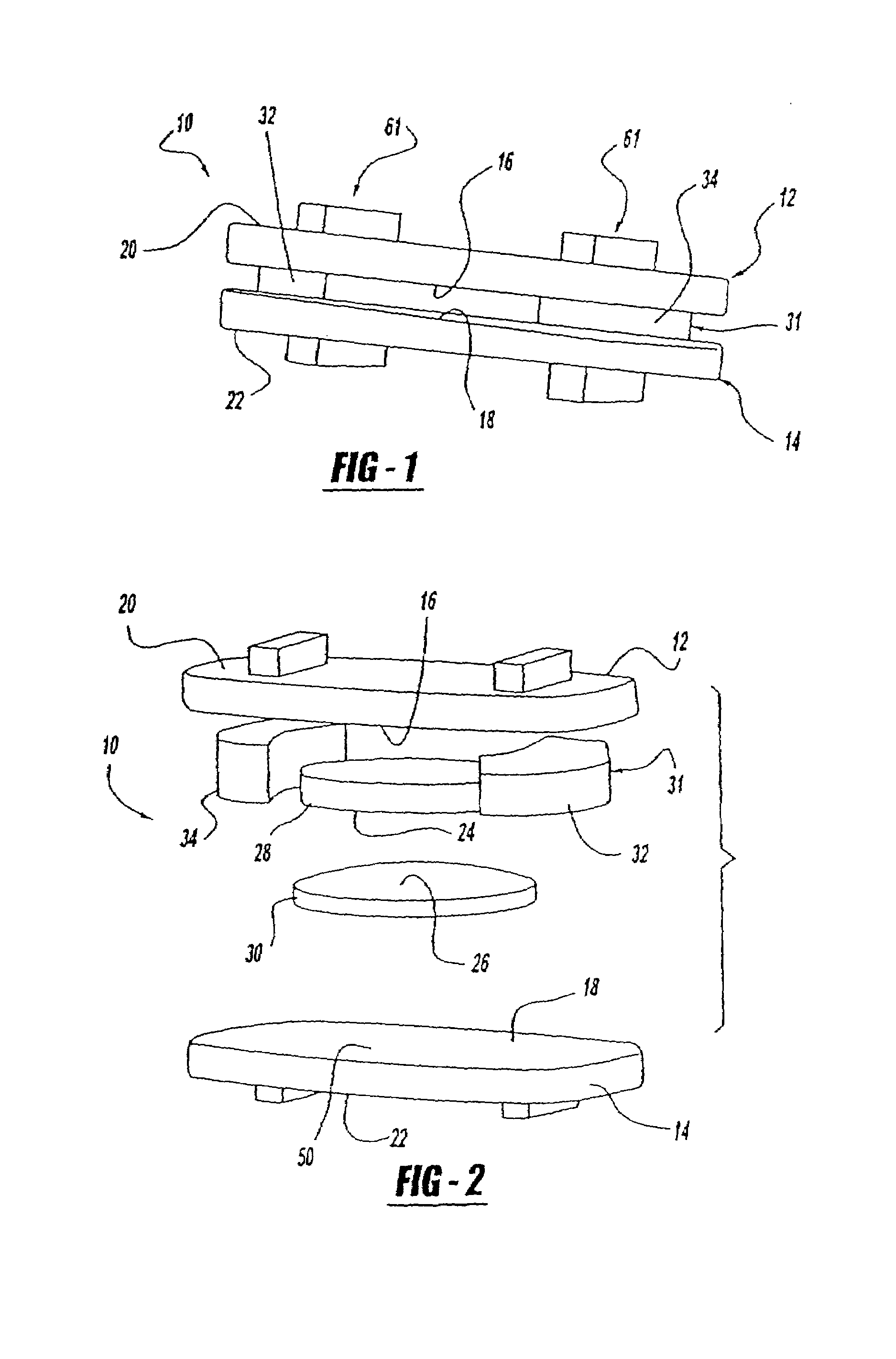
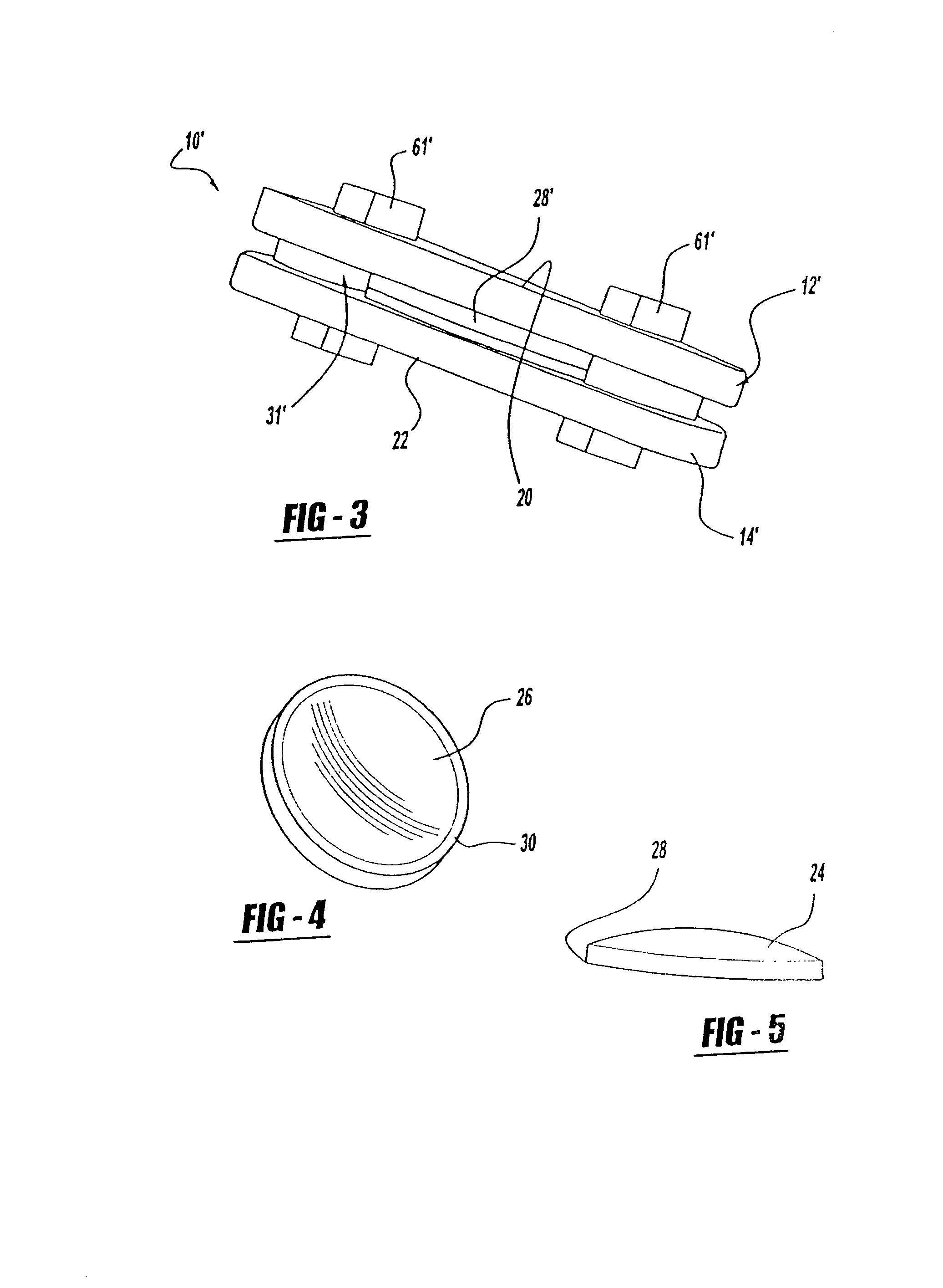
[0073]An artificial intervertebral disc constructed in accordance with the present invention is generally shown at 10 in the Figures. Similar structures of various embodiments are indicated by primed numerals in the Figures. The invention is an artificial intervertebral disc, sometimes referred to by other terminology in the prior art such as intervertebral spacer device, or spinal disc for replacement of a damaged disc in the spine. The invention restores motion to the damaged natural disc that allows for motion as well as cushioning and dampening. As described below in more detail, the present invention also allows changes to the artificial disc motion intraoperatively to adjust for specific anatomical conditions.

[0074]Referring to the Figures, the disc 10 includes an upper housing member generally shown at 12 and a lower housing member generally shown at 14. The housing members 12, 14 include spaced inner surfaces 16 and 18 facing each other and oppositely facing outer surfaces 2...


PUM

PropertyMeasurementUnit
perimeteraaaaaaaaaa
radiusaaaaaaaaaa
radius of curvatureaaaaaaaaaa

Abstract

An artificial intervertebral disc including housing members including spaced inner surfaces facing each other and oppositely facing outer surfaces for engaging spaced apart intervertebral surfaces; self-adjusting bearing mechanisms operatively disposed between the inner surfaces for moving relative to the housing members to adjust and compensate for vertebral disc motion; and positioning ring for controlling motion and position of the bearing mechanisms and for absorption of compressive loads. An artificial intervertebral disc including housing members having an oval recess on the inner surfaces; oval bearing mechanisms operatively disposed within the oval recess between the inner surfaces for moving relative to the housing members to adjust and compensate for vertebral disc motion; and oval positioning ring. A spring member for an artificial intervertebral disc including a substantially annular body having an axially extended bore therethrough defining a passageway.

Description

CROSS REFERENCE TO RELATED APPLICATIONS[0001]This patent application is a Continuation-In-Part application of U.S. patent application Ser. No. 10 / 653,540, filed Sep. 2, 2003, which is a Continuation-In-Part application of U.S. patent application Ser. No. 10 / 430,861, filed May 6, 2003, which are incorporated herein by reference in their entirety.BACKGROUND OF THE INVENTION[0002]1. Technical Field[0003]The present invention relates generally to a spinal implant assembly for implantation into the intervertebral space between adjacent vertebral bones to provide stabilization and continued postoperative flexibility and proper anatomical motion. More specifically, the present invention relates to an artificial intervertebral disc, sometimes referred to as an intervertebral spacer device, for functioning as a load sharing and bearing device for replacement of the damaged, decayed, or otherwise nonfunctioning intervertebral disc.[0004]2. Background of the Invention[0005]The spine is a compl...

Claims


Application Information

Patent Timeline
Patent Type & Authority Patents(United States)
IPC IPC(8): A61F2/44A61F2/30A61L27/00A61F2/00A61F2/28
CPCA61F2/4425A61F2/30767A61F2310/00796A61F2002/2817A61F2002/30014A61F2002/302A61F2002/30332A61F2002/30383A61F2002/30426A61F2002/30448A61F2002/30495A61F2002/305A61F2002/30563A61F2002/30578A61F2002/30604A61F2002/30616A61F2002/30649A61F2002/30841A61F2002/30884A61F2002/30904A61F2002/443A61F2220/0025A61F2220/0033A61F2220/005A61F2250/0018A61F2310/00023A61F2310/00029A61F2310/00179
Inventor RICHELSOPH, MARCCLIFT, JOSEPH
Owner AESCULAP IMPLANT SYST
Why Eureka
Try Eureka