Cyclone dust collector and vacuum cleaner therewith

a vacuum cleaner and dust collector technology, applied in the field of vacuum cleaners, can solve the problems of reducing the effectiveness of the cyclone dust collector, affecting dust separation, deteriorating suction strength, etc., and achieve the effects of preventing deterioration of the suction efficiency of the grille, and reducing the effect of turbulence flow

Inactive Publication Date: 2007-11-06
SAMSUNG GWANGJU ELECTRONICS CO LTD
View PDF22 Cites 38 Cited by
  • Summary
  • Abstract
  • Description
  • Claims
  • Application Information

AI Technical Summary

Benefits of technology

[0007]An aspect of the present invention is to solve at least the above problems and / or disadvantages and to provide at least the advantages described below. Accordingly, an aspect of the present invention is to provide a cyclone dust collector capable of preventing dust from attaching to a grill member and restraining generation of a turbulent flow in the cyclone dust collector.
[0015]Accordingly, the flanged part formed on the cyclone body enables the air current at the suction port to move in a wider radial motion, and therefore, the turbulent flow can be restrained from being generated, thereby improving dust-collecting efficiency.
[0016]Further, by existence of the blocking member, the dust included in air is not stuck to the grill member before being centrifuged, and this can prevent deterioration of suction efficiency of the grill member.

Problems solved by technology

In such a case, the centrifuged dust may not be collected in the dust receptacle 14 but stuck to the grill member 13 instead, thereby deteriorating suction strength and reducing the effectiveness of the cyclone dust collector.
Furthermore, turbulence in the air flow in the cyclone body 10, which can be generated in the cyclone dust collector for many reasons, also affects dust separation.
In addition, because the turbulent flow scatters away the dust already centrifuged, dust collection diminishes.

Method used


Image

  • Cyclone dust collector and vacuum cleaner therewith
  • Cyclone dust collector and vacuum cleaner therewith
  • Cyclone dust collector and vacuum cleaner therewith

Examples


Embodiment Construction

[0024]Hereinafter, certain embodiments of the present invention will be described in detail with reference to the accompanying drawing figures.

[0025]In the following description, drawing reference numerals are used for the same elements in different drawings. The embodiments described herein are only examples and are not intended to limiting the invention disclosed herein. Rather, the invention disclosed herein is defined by set forth in the appurtenant claims. Also, well-known functions and structures are not described in detail, since they would tend to obscure the claimed invention in unnecessary detail.

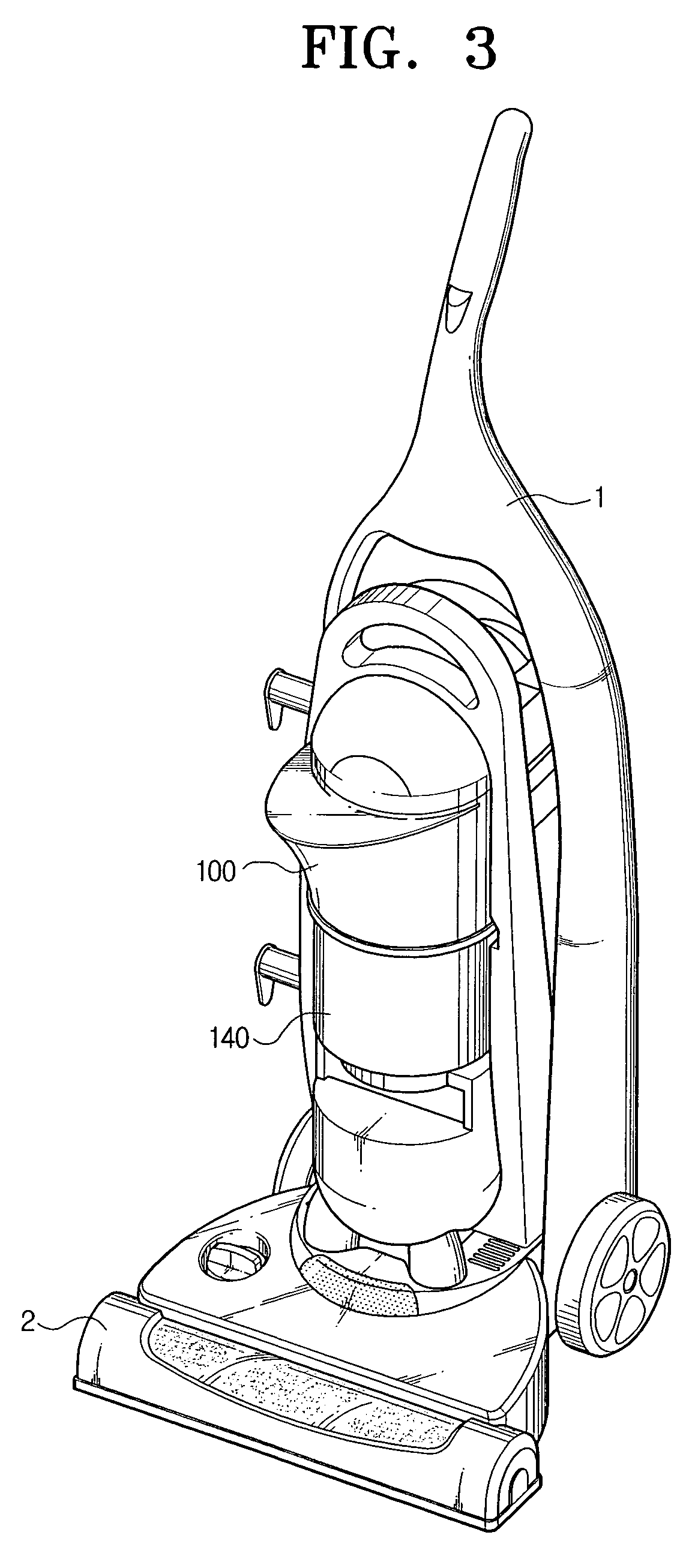
[0026]FIG. 3 is a perspective view of an upright-type vacuum cleaner having a cyclone dust collector 100 according to an embodiment of the present invention. The upright-type vacuum cleaner includes a cleaner body 1 having a vacuum suction means, such as a motor-driven fan (not shown), a suction brush 2 for drawing in dust from a surface being cleaned, and the cyclone dust collect...


PUM

PropertyMeasurementUnit
circumferenceaaaaaaaaaa
forceaaaaaaaaaa
inner circumferenceaaaaaaaaaa

Abstract

A cyclone dust collector and a vacuum cleaner having the same. The cyclone dust collector has a cyclone body shaped to have a relatively wider upper portion and a relatively narrower lower portion and also has a suction port and a discharge port, a grill member connected to the discharge port, a dust receptacle connected to the cyclone body, and a blocking member for partially blocking the grill member. Air drawn in through the suction port moves in an increasingly wider radial path as it travels upwardly to the discharge port, increasing the centrifugal force on suspended particles as they travel toward the discharge port. The shape of the cyclone body prevents turbulent flow from being generated. Dust is prevented by the blocking member from attaching to the grill member before being centrifuged, performance of the grill member is enhanced.

Description

CROSS-REFERENCE TO RELATED APPLICATIONS[0001]This application claims the benefit of Korean Patent Application No. 2004-66367, filed Aug. 23, 2004, in the Korean Intellectual Property Office, the disclosure of which is incorporated herein by reference.FIELD OF THE INVENTION[0002]The present invention relates to a vacuum cleaner. More particularly, the present invention relates to a cyclone dust collector and a vacuum cleaner having the same.BACKGROUND OF THE INVENTION[0003]Generally, a cyclone dust collector in a vacuum cleaner draws in dust-laden air, forms a whirling or cyclonic air current that separates dust from the dust-laden air by a centrifugal force generated from the whirling air current and collects the separated dust particles in a bin or trap for later disposal. In general, cyclone dust collectors do not pass dust-laden air through an air filtration element.[0004]FIGS. 1 and 2 are respectively, a perspective view and a cross-sectional view, of a prior art conventional cy...

Claims


Application Information

Patent Timeline
Patent Type & Authority Patents(United States)
IPC IPC(8): B01D45/12A47L9/16B04C5/081B04C5/13
CPCA47L9/1608A47L9/1666B04C5/13B04C5/081Y10S55/03A47L9/16
Inventor OH, JANG-KEUNHEO, YONG SEOK
Owner SAMSUNG GWANGJU ELECTRONICS CO LTD
Why Eureka
Try Eureka