
Processing equipment

Active Publication Date: 2007-11-06
LAPIS SEMICON CO LTD
View PDF7 Cites 3 Cited by
  • Summary
  • Abstract
  • Description
  • Claims
  • Application Information

AI Technical Summary

Benefits of technology

[0011]Accordingly, in one aspect of the present invention, a processing equipment for reducing an hardened photoresist on the nozzle is provided. The processing equipment includes a chamber, an airflow generator which generates a downward airflow in the chamber, a stage in the chamber, a nozzle which is arranged above the stage. The nozzle has a protector which is arranged around a supply port of the nozzle. The protector protects the supply port from the downward airflow.

Problems solved by technology

If the hardened phoresist falls on the semiconductor wafer, the photoresist layer may be formed non-uniformly on the semiconductor wafer.
However, exposing the nozzle to the downward airflow increases the chances of hardening the photoresist.

Method used


Image

  • Processing equipment
  • Processing equipment
  • Processing equipment

Examples


first embodiment

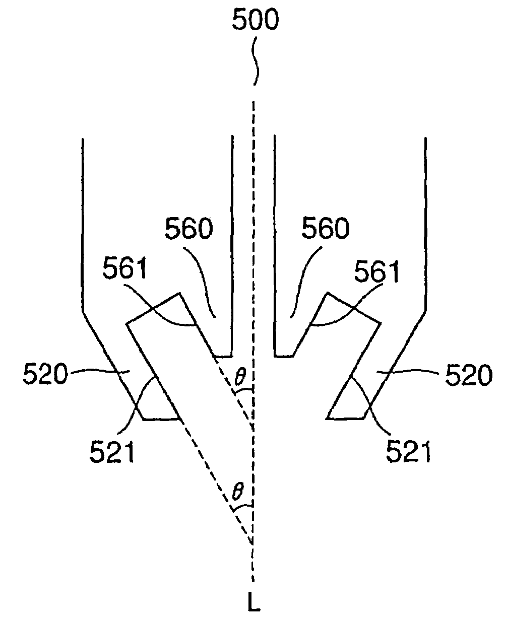
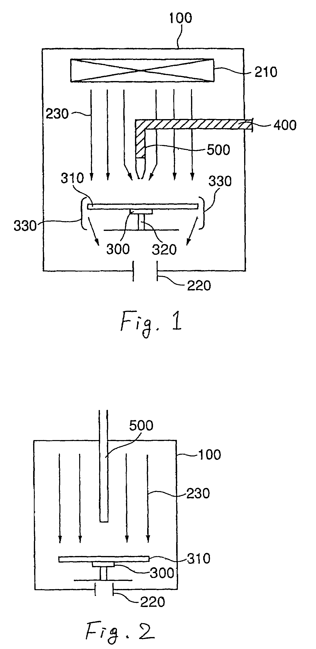
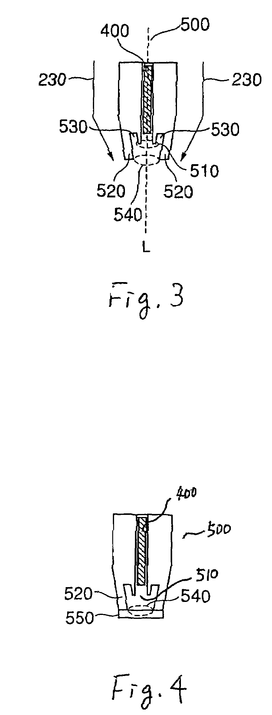
[0028]FIG. 1 is a cross-sectional view showing processing equipment of the present invention. FIG. 2 is a cross-sectional view showing processing equipment of a first alternative embodiment of the present invention. FIG. 3 is a cross-sectional view showing a lower end of the nozzle 500 of the present invention. FIG. 4 is a cross-sectional view showing a lower end of the nozzle 500 of the alternative embodiment of the present invention.

[0029]The processing equipment includes a chamber 100 and an airflow generator which generates a downward airflow 230 in the chamber 100. The airflow generator includes an air filter 210 formed in the upper portion of the chamber 100 and an exhaust port 220 formed in the lower portion of the chamber 100.

[0030]Air is supplied from outside of the chamber 100 to the air filter 210. The air flows to the bottom of the chamber 100. The air is exhausted from the exhaust port 220. As a result, downward airflow 230 is generated.

[0031]A stage 300 for mounting a ...

second embodiment

[0052]The processing equipment of the second embodiment includes a pot 600 filled by the gas 410. The pot 600 includes a solvent area 610 in which is put the solvent 611 of the photoresist 400 and a gas area 620 which is filled by the gas such as thinner made by the solvent 611.

[0053]The pot 600 is formed on a side wall of the nozzle 500. The gas area 620 of the pot 600 is coupled to the space 660 via a through hole 570. Accordingly, the photoresist 400 adhered at the supply port 510 is dissolved by the gas 410, so that the chances the photoresist 400 hardening is reduced.

[0054]The nozzle 500 has the protector 520 for protecting the space 660 from the downward airflow 230. As a result, a chance that the gas 410 runs out from the space 660 is reduced. That is, the gas 410 is kept in the space 660 when the nozzle 500 is exposed to the downward airflow 230.

[0055]The nozzle 500 has the cap 550 at the lower end of the protector 520. When the photoresist 400 is supplied from the supply po...


PUM


Abstract

A processing equipment includes a chamber, an airflow generator which generates a downward airflow in the chamber, a stage in the chamber, a nozzle which is arranged above the stage. The nozzle has a protector which is arranged around a supply port of the nozzle. The protector protects the supply port form the downward airflow.

Description

CROSS REFERENCE TO RELATED APPLICATION[0001]A claim of priority under 35 U.S.C. §119 is made to Japanese Patent Application No. 2003-120507, filed Apr. 24, 2003, which is herein incorporated by reference in its entirety for all purposes.BACKGROUND OF THE INVENTION[0002]1. Field of the Invention[0003]The present invention relates to a processing equipment with a nozzle.[0004]2. Description of the Related Art[0005]A conventional processing equipment for a semiconductor wafer includes a chamber, an airflow generator for generating a downward airflow, a stage for mounting a semiconductor wafer, and a nozzle for supplying a photoresist to the semiconductor wafer.[0006]The photoresist is supplied from the nozzle to the semiconductor wafer. The supplied photoresist is extended to the entire surface of the semiconductor wafer by rotating the semiconductor wafer. As a result, a photoresist layer is formed on the semiconductor wafer.[0007]Since the semiconductor wafer is rotated, a part of th...

Claims


Application Information

Patent Timeline
IPC IPC(8): B05B15/02B05B15/04B05B15/12B05D1/26B05C5/00B05C11/08B05C15/00B05D7/00H01L21/00H01L21/027
CPCH01L21/6715
Inventor JONOSHITA, AKIRA
Owner LAPIS SEMICON CO LTD
Learn More