Phase locked loop frequency synthesizer

a phase locked loop and frequency synthesizer technology, applied in the direction of oscillator, pulse automatic control, pulse technique, etc., can solve the problems of high speed responsibility, difficulty in realizing the demands of high speed responsibility and “wider bandwidth” at the same time, and the inability to completely match the vco frequency with the required frequency, etc., to achieve the effect of reducing the number of repetition time for the convergence, and reducing the number of repetition

Inactive Publication Date: 2007-11-06
RENESAS ELECTRONICS CORP
View PDF14 Cites 16 Cited by
  • Summary
  • Abstract
  • Description
  • Claims
  • Application Information

AI Technical Summary

Benefits of technology

[0043]In the phase locked loop frequency synthesizer of the present invention, said fixed-value capacitor controlling unit may include: a first counter which counts said first signal; a second counter which counts the count number of said second counts while said first counter counts predetermined numbers of said first signal; a calculation unit that calculates an ideal value for said count number of said second signal while said predetermined numbers of said first signal is counted; and a comparator which compares said count number counted by said second counter and said ideal value calculated by said calculation unit to output differential operator thereof, and said fixed-value capacitor controlling unit may correct said selection signal based on said differential operator to output to voltage control oscillating.
[0052]According to the present invention, since an initial value of the selection signal to select the combination of the fixed-value capacitors to be connected to the LC-tank circuit in parallel is obtained based on the predetermined frequency dividing ratio setting signal, the number of repetition time for the convergence can be reduced.
[0053]According to the present invention, since the selection signal is corrected by the feedback according to the difference between the present actual value and the calculated expected value, the number of repetition time for the convergence can be reduced.
[0054]Furthermore, according to the present invention, since the judgment accuracy can be set externally, the number of repetition time for the convergence can be reduced. Hence, according to the present invention, the number of repetition time for the convergence can be reduced in the digital tuning process so that two demands required for the phase locked loop frequency synthesizer, “high-speed responsibility” and “wider bandwidth”, can be compatible with the shortest convergence time.

Problems solved by technology

Further, the VCO frequency fVCO cannot be completely matched with the required frequency as the VCO frequency fVCO changes discretely.
Therefore, it has been a problem in the conventional PLL frequency synthesizer that the demands of “high-speed responsibility” and “wider bandwidth” are incompatible because the time required for the discretely adjusting process for the VCO frequency fVCO increases in proportion to “wider bandwidth”.
In addition, as for the techniques described in the publications mentioned above, it is difficult to actualize the demands of “high-speed responsibility” and “wider bandwidth” at the same time.

Method used


Image

  • Phase locked loop frequency synthesizer
  • Phase locked loop frequency synthesizer
  • Phase locked loop frequency synthesizer

Examples


first embodiment

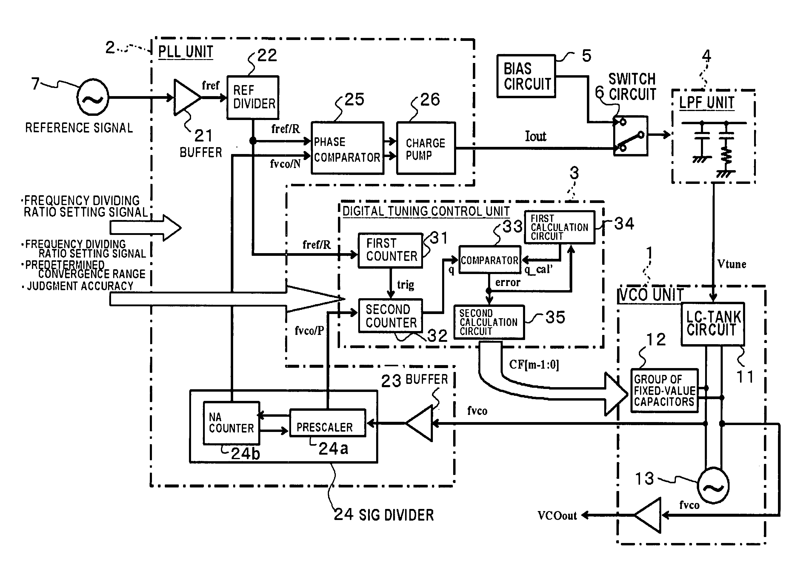
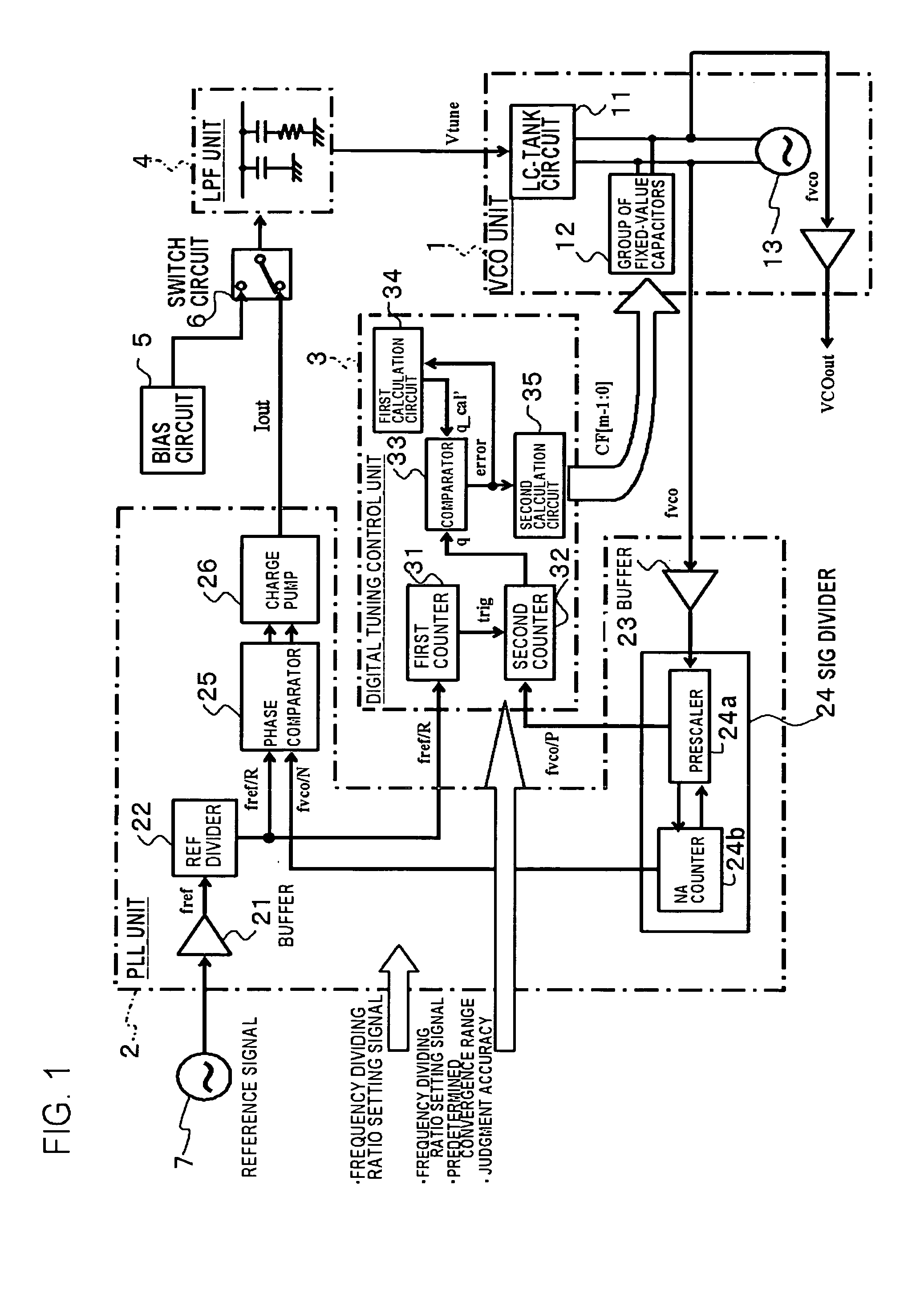
[0073]FIG. 1 shows a block diagram of a PLL frequency synthesizer of the first embodiment according to the present invention.

[0074]As shown in FIG. 1, the PLL frequency synthesizer of the embodiment includes an oscillator unit (VCO unit) 1, a phase control unit (PLL unit) 2, a digital tuning control unit 3, a low pass filter unit (LPF unit) 4, a bias circuit 5, and a switch circuit 6.

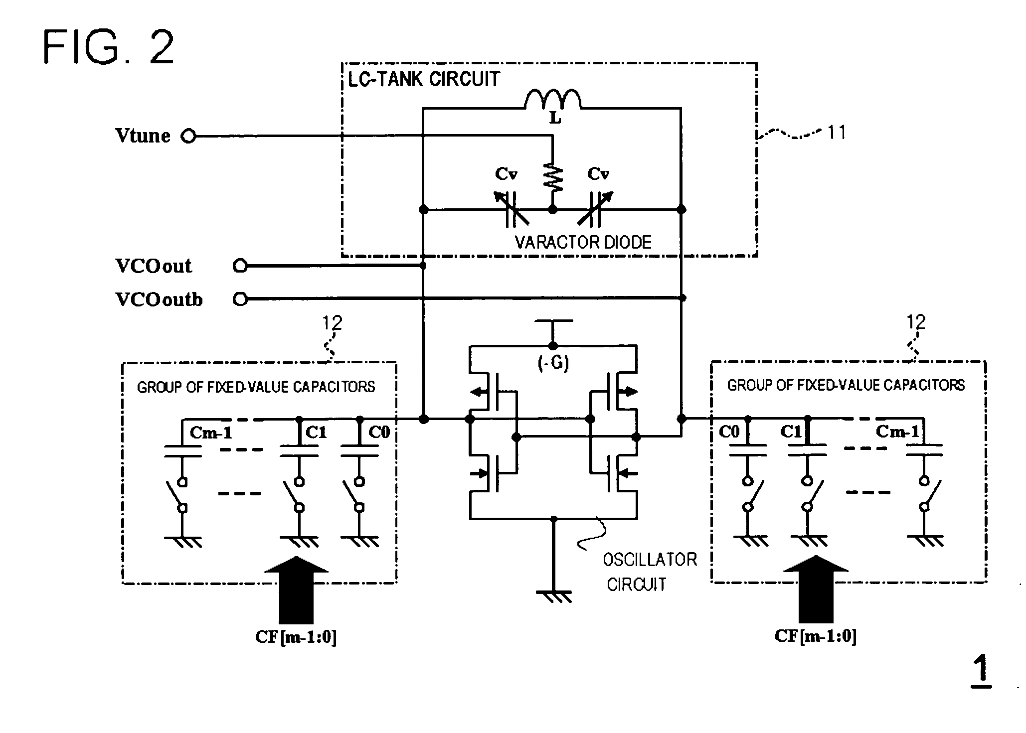
[0075]The VOC unit 1 includes an LC-tank circuit 11, a group of fixed-value capacitors 12 and an oscillator circuit 13.

[0076]FIG. 2 shows a detailed structure of the VCO unit 1 shown in FIG. 1. The LC-tank circuit 11 includes an inductor L and two variable capacitors Cv each of which including a varactor diode, where the variable capacitors Cv are connected in series with each other and the inductor L is connected in parallel to the variable capacitors Cv. Thus, the parallel resonance circuit is constructed. Here, the VCO unit 1 includes two groups of fixed-value capacitors 12 each of which including a ...

second embodiment

[0155]The PLL frequency synthesizer of the present invention includes an oscillator (LC oscillator) with an LC resonator. The VCO frequency of the LC oscillator is determined by the following equation.

fVCO=1 / 2π√(L×C)

[0156]Where π is Ludolphian number. When the LC oscillator is formed on a semiconductor substrate, variations of the inductor (L) and the capacitor (C) generated in the manufacturing process cause variations of the characteristics of the VCO frequency fVCO for the same selection signal CF[m-1:0] as shown in FIG. 8.

[0157]The initial value CF—0 is calculated by the first calculation circuit 34 based on the above described internal ideal formula shown as the definition [10]. The variations of the products caused during the manufacturing process, as shown in FIG. 8, causes the error between the calculated initial value CF—0 and actual characteristics of the relationship between the selection signal CF[m-1:0] and the VCO frequency fVCO. Such the error causes, in turn, increas...


PUM


Abstract

The phase locked loop frequency synthesizer, includes: an LC-tank circuit which includes an inductor and a variable capacitor in which the capacity changes depending on the input voltage; a group of fixed-value capacitors which is connected to the LC-tank circuit in parallel; a voltage control oscillating unit which outputs a signal with a frequency determined by the LC-tank circuit and the group of fixed-value capacitors; a phase control unit which generates an output current based on an error operator between a first signal with a divided frequency of a reference frequency and a second signal with a divided frequency of the frequency output from the voltage control oscillating unit; a fixed-value capacitor controlling unit which outputs a selection signal which determines the combination of the fixed-value capacitors to be connected to the LC-tank circuit in parallel based on a frequency dividing ratio setting signal including information about dividing ratio of the second signal, and controls the connection of the fixed-value capacitors selected from the group of fixed-value capacitors based on the selection signal to the LC-tank circuit in parallel; and a variable capacitor controlling unit which selects either one of a fixed bias voltage and the voltage obtained by converting the output current output from the phase control unit and inputs the selected voltage to the variable capacitor of the LC-tank circuit.

Description

[0001]This application is based on Japanese Patent application No. 2004-108268, the content of which is incorporated hereinto by reference.BACKGROUND OF THE INVENTION[0002]1. Field of the Invention[0003]The present invention relates to a PLL frequency synthesizer including a voltage controlled oscillator and a phase control loop which controls the oscillation frequency of the voltage controlled oscillator, integrated on a semiconductor device, and a method of automatically selecting the oscillation frequency of a voltage controlled oscillator.[0004]2. Description of the Related Art[0005]In various wireless communication systems, frequencies in receiving signals and transmitting signals vary in accordance with the communication systems. A PLL frequency synthesizer including an oscillator and a phase locked loop (PLL) is capable of determining the frequency accepted in the communication system.[0006]FIG. 13 shows an example of a conventional PLL frequency synthesizer.[0007]The convent...

Claims


Application Information

Patent Timeline
Patent Type & Authority Patents(United States)
IPC IPC(8): H03B5/12H03L7/099H03B5/06H03L7/10
CPCH03L7/099H03L7/08
Inventor URAKAWA, TATSUYA
Owner RENESAS ELECTRONICS CORP
Why Eureka
Try Eureka