Optical device capable of emitting photons and method for its manufacture

Active Publication Date: 2011-03-29
KK TOSHIBA
View PDF11 Cites 7 Cited by
  • Summary
  • Abstract
  • Description
  • Claims
  • Application Information

AI Technical Summary

Benefits of technology

[0032]The device may also be configured such that the light is emitted in the plane of the layer or layers. This can be achieved by reducing the number of repeats of the pattern in the direction in the plane along which light emission

Problems solved by technology

Normal light sources suffer from random fluctuations in the photon emission rate at low intensities due to shot noise.
This noise limits the sensitivity of many optical techniques where single photons are detected.
A significant number of these multi-photon emissions would seriously impinge on the security of the device for quantum cryptography.
The second problem is that most of the periods are empty and hence carry no information.
Thus, the time which it takes to send the key is increased, and also, the maximum distance over which it can be transmitted is limited.
The distance limitation problem arises from the fact that optical quantum cryptography is only effective when the rate of detected photons is m

Method used


Image

  • Optical device capable of emitting photons and method for its manufacture
  • Optical device capable of emitting photons and method for its manufacture
  • Optical device capable of emitting photons and method for its manufacture

Examples


Embodiment Construction

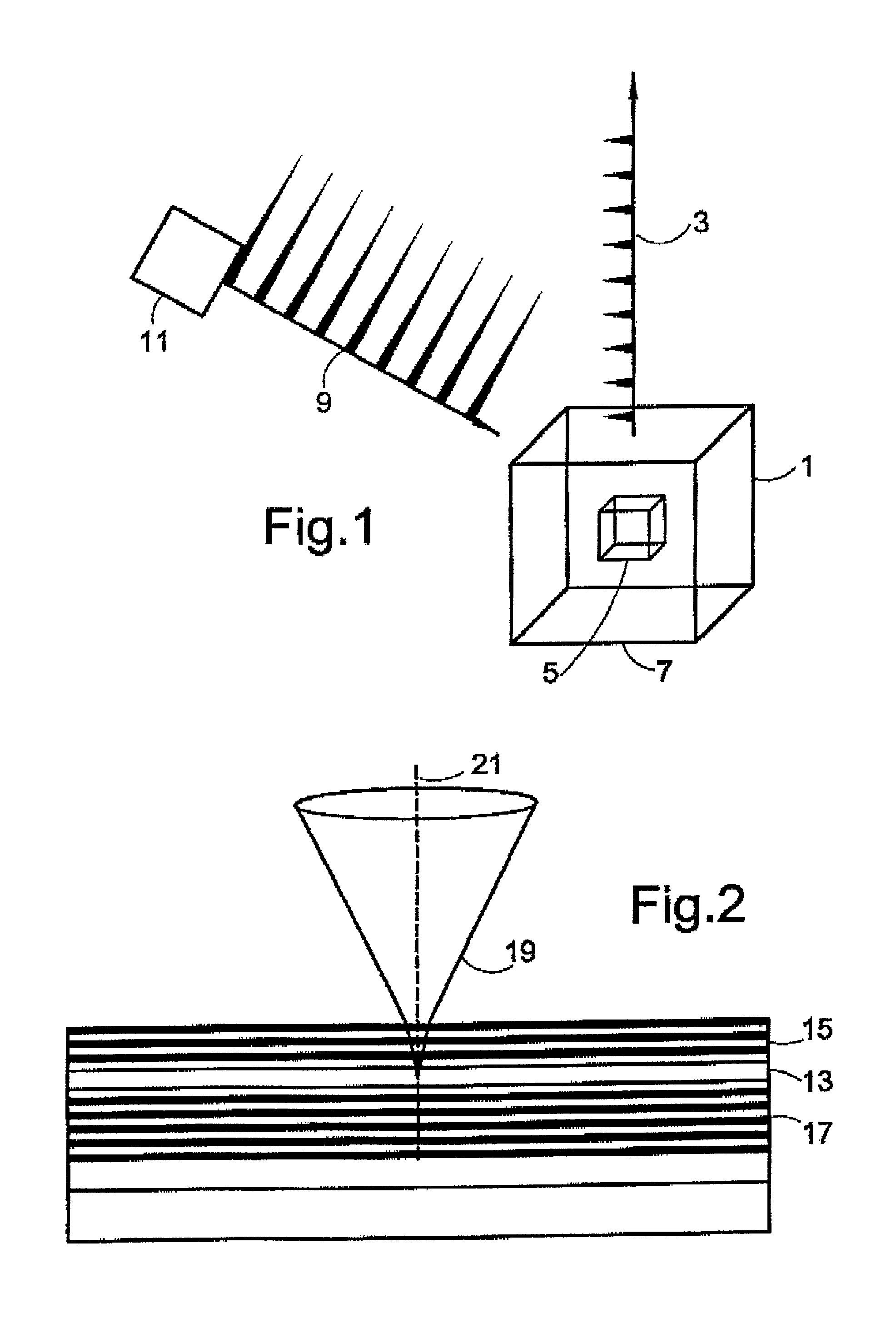
[0096]FIG. 1 shows a schematic of a single-photon emitter 1 directing its output in a predetermined direction 3. The optical source comprises a quantum dot 5 which is located within a three-dimensional mirror cavity 7.

[0097]The quantum dot 5 is configured to emit a stream of regularly spaced single photons or emit pulses of multiple photons in response to irradiation by pulsed beam 9 from pulsed laser diode 11. An example of how this is achieved will be described with reference to FIG. 6. In the absence of an optical cavity, the quantum dot 5 will irradiate isotropically. Therefore, only a small amount of the radiation will be emitted in direction 3. However, use of the three dimensional mirror cavity 7 allows the radiation emitted by quantum dot 5 to be directed in predetermined direction 3. This radiation can be efficiently collected by a fibre optic cable, or the optic.

[0098]FIG. 2 shows a one-dimensional cavity. The cavity 13 is defined by an upper Bragg mirror 15 and a lower Br...


PUM


Abstract

An optical device which can operate as a single photon emitter 1, comprising a three dimensional optical cavity 7 which spatially confines a photon to the order of the photon wavelength in all three dimensions. The cavity 7 is configured to define preferred emission direction for photons entering the cavity. A photon can be supplied to the cavity using a quantum dot 5. Strong coupling can occur between the cavity 7 and the quantum dot 5 which causes the formation of two hybridised modes. Switching on an off the coupling by irradiating the device with radiation having an energy equal to that of one of the hybridised modes allows the device to act as an optical switch.

Description

BACKGROUND OF THE INVENTION[0001]The present invention relates to au optical device which can be configured as a source which emits single or multiple photons at a predetermined time or which can be configured as an optical switch.[0002]As an optical source, the device is capable of emitting pulses of n-photons where n is controllable and is an integer of at least 1. More specifically, the present invention is concerned with such a device which has means or directing photons such that they can be efficiently collected by an external medium such as a fibre optic cable and a method of making such a device. The present invention can be used to increase the efficiency of any light emitter.[0003]There is a growing need for single photon sources for use in optical quantum cryptography where, for example, a security key for an encryption algorithm is delivered by a stream of single photons which are regularly spaced in time. It is essential for the security of this technique that each bit ...

Claims


Application Information

Patent Timeline
IPC IPC(8): H01L33/00G02B6/122G02B6/35H01S5/04H01S5/10H01S5/34
CPCB82Y20/00B82Y30/00G02B6/1225H01S5/10H01S5/041H01S5/105H01S5/3412G02F1/0126G02F2203/15H01S5/11
Inventor SHIELDS, ANDREW JAMES
Owner KK TOSHIBA
Why Eureka
Try Eureka