Dual mode digital imaging and camera system

a digital imaging and camera system technology, applied in the field of electronic photography, can solve the problems of less adaptability of processing, less camera input, and more expensive cameras, and achieve the effect of optimizing the image quality of a relatively high resolution rgb output image, reducing processing time, and low resolution

Inactive Publication Date: 2007-11-06
MONUMENT PEAK VENTURES LLC
View PDF6 Cites 58 Cited by
  • Summary
  • Abstract
  • Description
  • Claims
  • Application Information

AI Technical Summary

Benefits of technology

[0010]The advantage is that the motion mode processing, which is performed using algorithms and software approaches designed to minimize processing time, nonetheless produces an entirely adequate relatively low resolution YUV image appropriate for applications such as videoconferencing. The still mode processing, on the other hand, uses more elaborate algorithms to optimize the image quality of a relatively high resolution RGB output image. Instead of “point” processing as in the motion mode, the still mode uses spatial processing as well as point processing, for example, by providing “edge enhanced” pixel values using a two-dimensional finite impulse response (FIR) filter operating on neighboring pixels. The rendition of the output image is substantially the same in both modes since the same user controls for contrast, color saturation, brightness, hue and white balance affect both processing modes via the different processing paths.

Problems solved by technology

This preview processing is preferably done using hardwired circuitry, which makes the camera more expensive and makes the processing less adaptable.
The camera does not allow the user to affirmatively elect between the motion and the still mode.
While describing two modes of operation in some cases, the prior art does not allow for optimization of processing in the separate modes.

Method used


Image

  • Dual mode digital imaging and camera system
  • Dual mode digital imaging and camera system
  • Dual mode digital imaging and camera system

Examples


Embodiment Construction

[0019]Because imaging devices employing electronic sensors are well known, the present description will be directed in particular to elements forming part of, or cooperating more directly with, apparatus in accordance with the present invention. Elements not specifically shown or described herein may be selected from those known in the art. Certain aspects of the embodiments to be described may be provided in software. Given the system as described in the following materials, all such software implementation needed for practice of the invention is conventional and within the ordinary skill in such arts.

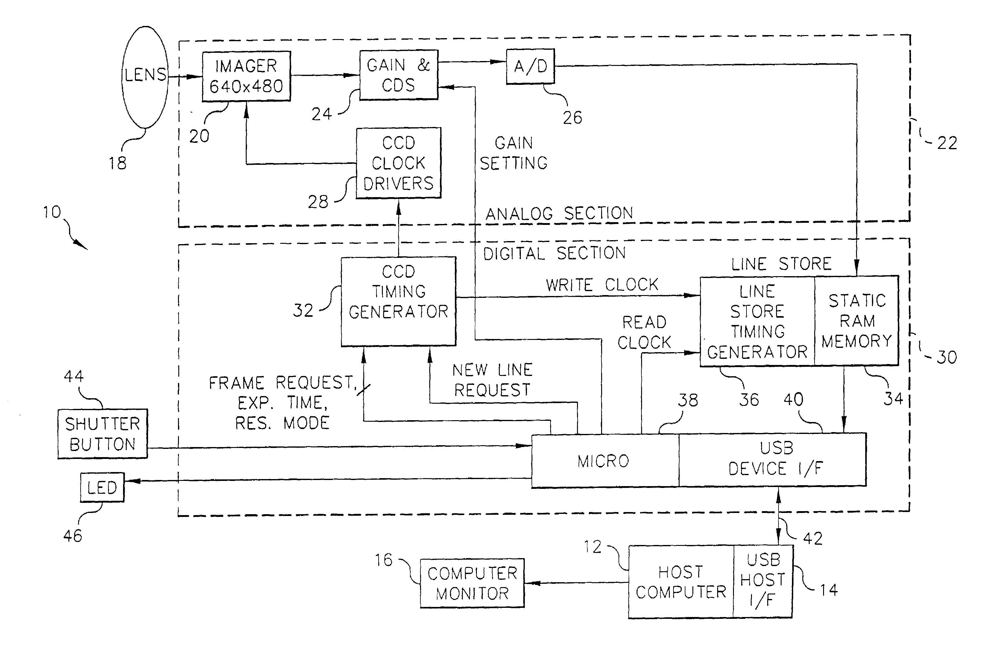
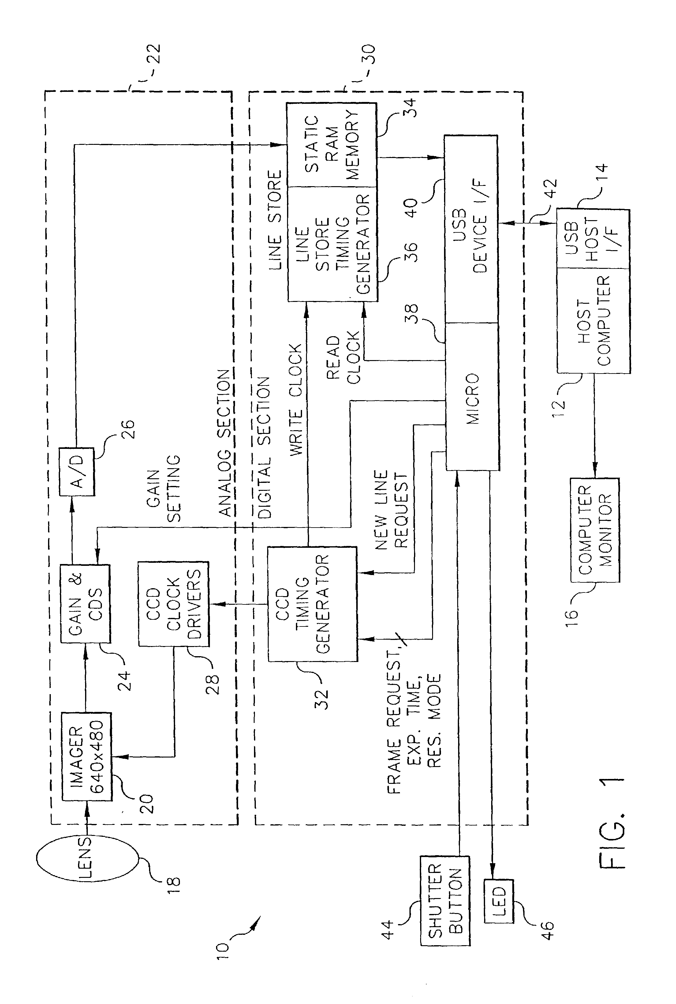
[0020]A block diagram of a digital imaging system according to the invention is shown in FIG. 1. The system includes a camera 10 connected to a host computer 12 via a USB (universal serial bus) cable 42 connected to a USB digital host interface 14, which also provides power to the camera 10. USB is a well-known shared bus that can be connected to other devices, such as keyboards, prin...


PUM


Abstract

A dual mode digital imaging system has a still processing mode that produces an output image in a first color space and a motion processing mode that produces an output image in a second color space, in particular a first color space that is RGB and a second color space that is YUV. The digital imaging system includes a dual mode digital camera for use with a computer and a processing application for running on the computer, wherein the motion mode processing is relatively less complex than the still mode processing although at least one common control parameter is used to control both modes. The motion mode processing, which is performed using algorithms and software approaches designed to minimize processing time, nonetheless produces an entirely adequate relatively low resolution YUV image appropriate for applications such as videoconferencing. The still mode processing, on the other hand, uses more elaborate algorithms to optimize the image quality of a relatively high resolution RGB output image.

Description

CROSS-REFERENCE TO RELATED APPLICATION(S)[0001]The present application is a continuation of application Ser. No. 08 / 712,692, filed Sep. 12, 1996 now abandoned.[0002]Reference is made to commonly assigned copending application Ser. No. 08 / 712,704, entitled “Multi-Mode Digital Camera with Computer Interface Using Data Packets Combining Image and Mode Data,” filed in the names of J. A. Endsley, T. N. Berarducci and W. E. Prentice on the same date herewith, and subsequently issued as U.S. Pat. No. 6,005,613; and Ser. No. 08 / 712,689, entitled “Timing Control for a Digitally Interfaced Camera Using Variable Line Readout Intervals,” filed in the names of J. A. Endsley, T. N. Berarducci, and K. A. Parulski on the same date herewith, and subsequently issued as U.S. Pat. No. 5,841,471; each of which is assigned to the assignee of the present application.FIELD OF THE INVENTION[0003]The invention relates generally to the field of electronic photography, and in particular to a digital camera cap...

Claims


Application Information

Patent Timeline
Patent Type & Authority Patents(United States)
IPC IPC(8): H04N5/225G03B17/16H04N5/232H04N9/00H04N9/04
CPCH04N9/045H04N5/232H04N23/661H04N23/843H04N25/134
Inventor PRENTICE, WAYNE E.BERARDUCCI, THOMAS N.PARULSKI, KENNETH A.
Owner MONUMENT PEAK VENTURES LLC
Why Eureka
Try Eureka