Method and apparatus for automatic crossover and parallel detect

a parallel detection and automatic crossover technology, applied in the network field, can solve the problems of inadvertent use of wrong cable type, inability to auto-crossover, and inability to automatically cross-over, so as to achieve the effect of enabling autonegotiation and parallel detection avoiding inability to detect parallel,

Active Publication Date: 2007-11-06
MARVELL ASIA PTE LTD
View PDF24 Cites 31 Cited by
  • Summary
  • Abstract
  • Description
  • Claims
  • Application Information

AI Technical Summary

Problems solved by technology

The use of two different types of cables increases customer equipment inventory and may lead to the inadvertent use of the wrong type of cable.
Legacy PHY devices are typically autonegotiation enabled but are not auto-crossover enabled.
As currently defined, the auto-crossover sample timer is incompatible with the autonegotiation wait timer.

Method used


Image

  • Method and apparatus for automatic crossover and parallel detect
  • Method and apparatus for automatic crossover and parallel detect
  • Method and apparatus for automatic crossover and parallel detect

Examples


Embodiment Construction

[0031]The following description of the preferred embodiment(s) is merely exemplary in nature and is in no way intended to limit the invention, its application, or uses.

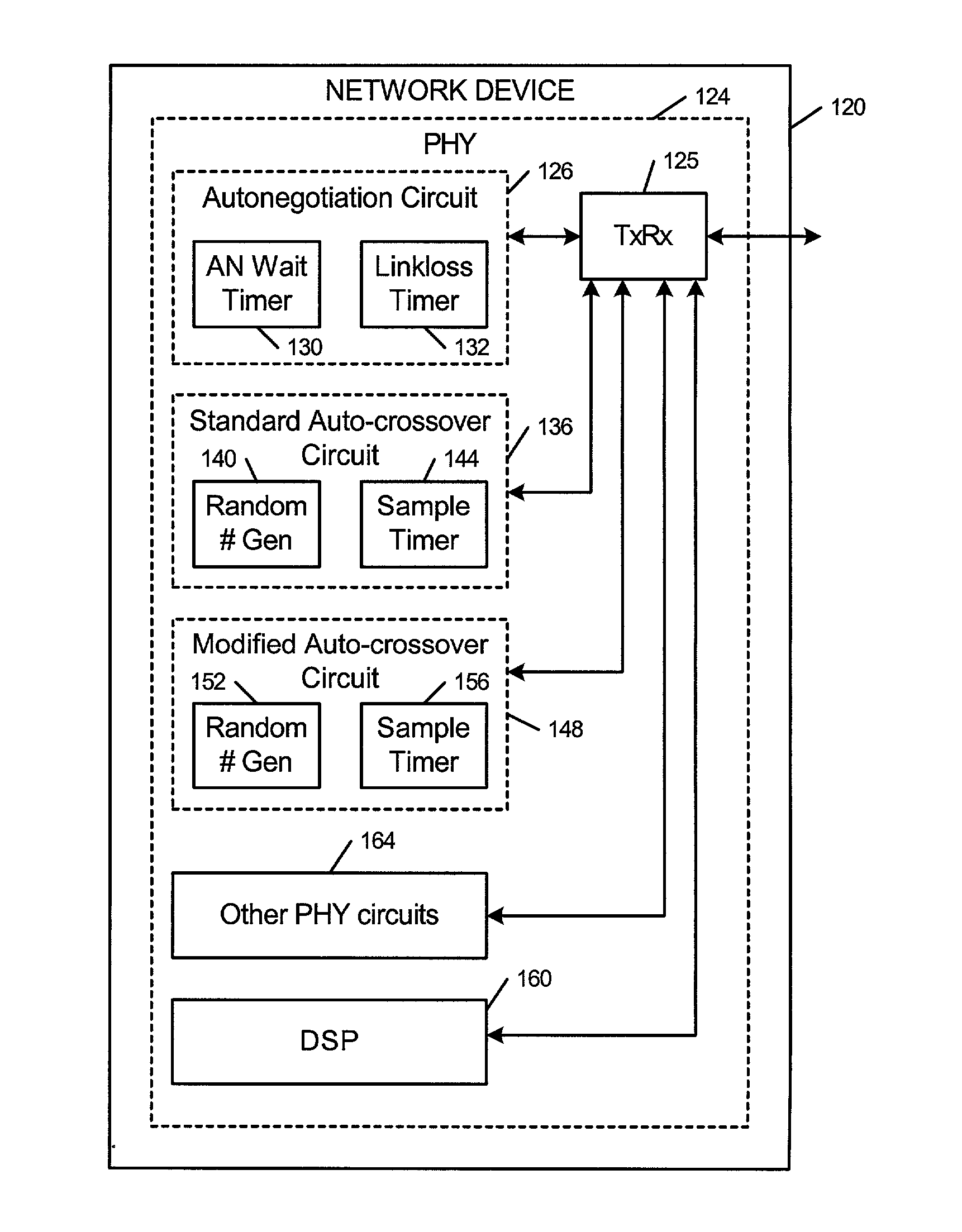
[0032]When a first PHY is autonegotiation enabled and a second PHY is operating in a forced 100BASE-TX or 10BASE-T mode, a modified auto-crossover circuit according to the present invention is employed in the second PHY. The modified auto-crossover circuit of the second PHY increases a period of the sample timer. The period of the sample timer of the auto-crossover of the second PHY is set to a value that is greater than or equal to the period of an autonegotiation wait timer. This allows the autonegotiation circuit of the first PHY a sufficient amount of time to establish a link.

[0033]When one PHY is auto-crossover enabled and the other PHY is not, the conventional auto-crossover circuit requires an average of approximately 2 sample timer periods before a configuration switch occurs. In a worst case scenario, the con...


PUM


Abstract

A physical layer of an Ethernet network device includes first, second, third and fourth terminals. An autonegotiation circuit includes an autonegotiation wait timer having an autonegotiation wait period. An auto-crossover circuit selectively configures the first and second terminals as one of a transmitter and a receiver and the third and fourth terminals as the other of the transmitter and receiver. The auto-crossover circuit includes a sample timer having a sample timer period that has a value that is greater than or equal to the autonegotiation wait period. The auto-crossover circuit includes a random number generator that communicates with the sample timer and generates n random numbers. The sample timer selects one of n sample timer periods based on the generated random number. The n sample timer periods have values that are greater than or equal to the autonegotiation wait period.

Description

FIELD OF THE INVENTION[0001]The present invention relates to networks, and more particularly to autonegotiation and auto-crossover circuits within a physical layer of devices that are connected by an Ethernet network.BACKGROUND OF THE INVENTION[0002]Devices operating according to 100BASE-TX or 10BASE-T in an Ethernet network are connected by four pairs of wires. Only two pairs of wires are required. Referring now FIGS. 1 and 2, first and second network devices or network devices 10 and 12 include physical layers (PHYs) 14 and 16 that are connected. For example, the network device 10 can be a personal computer or printer and the network device 12 can be a network switch. Each of the network devices 10 and 12 includes at least two pairs of twisted pair wires that are labeled 1, 2 and 3, 6 in FIGS. 1 and 2.[0003]When in an MDI configuration, the PHY 14 has a first pair 1, 2 that is configured as a transmitter 20 and a second pair 3, 6 that is configured as a receiver 24. When in an MDI...

Claims


Application Information

Patent Timeline
Patent Type & Authority Patents(United States)
IPC IPC(8): H04L12/56
CPCG06F13/4072
Inventor CAMPANA, FRANCISLO, WILLIAM
Owner MARVELL ASIA PTE LTD
Why Eureka
Try Eureka