Dual modality tomography apparatus with a patient support device

a tomography and support device technology, applied in the field of tomography apparatus, can solve the problem that the support plate stiffness is only possible with a high cos

Inactive Publication Date: 2007-11-06
SIEMENS AG
View PDF9 Cites 19 Cited by
  • Summary
  • Abstract
  • Description
  • Claims
  • Application Information

AI Technical Summary

Benefits of technology

[0006]An object of the present invention is to provided a tomography apparatus that allows data acquisitions with at least two acquisition systems arranged one after the other to be accomplished in a simple manner at the respective acquisition positions under essentially the same acquisition conditions.
[0009]The inventive tomography apparatus thus enables the use of a standard support plate which is elastically-deformable to a certain degree, such that a cost-intensive stiffening can be foregone.
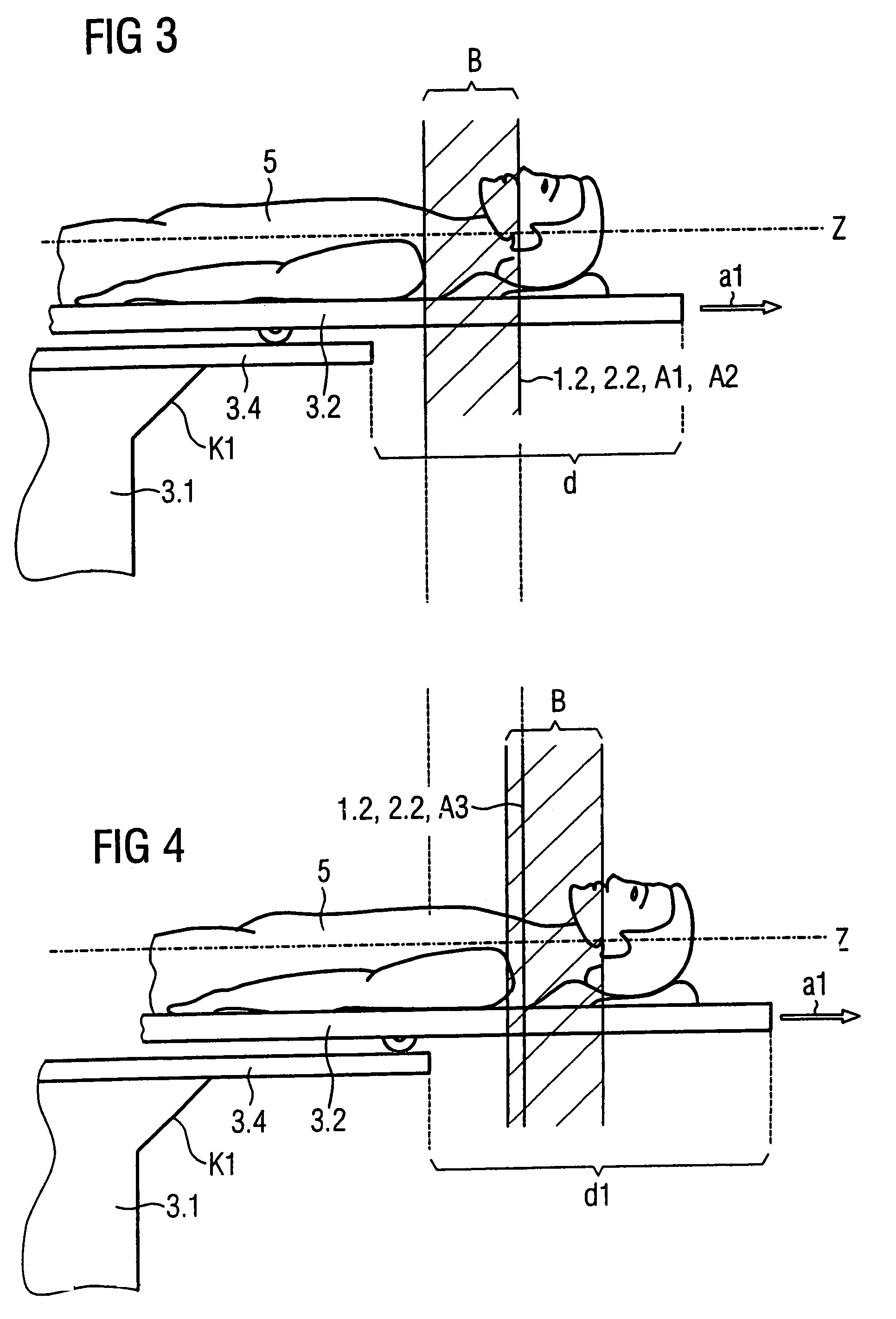
[0012]Starting from the first or the second acquisition position, data from the scan region can be acquired solely by displacement of the support plate. Given displacement of the support plate, the base remains in an unchanged position relative to the floor so that the same deflection of the support plate within the entire scan region also exist at each acquisition position in each acquisition system. Thus, a simple geometric fusion of the respective images acquired from the acquisition systems is possible for the entire scan region.
[0013]The first acquisition system preferably is an x-ray computed tomography (CT acquisition system and the second acquisition system preferably is a positron emission (PET) acquisition system. The images that can be generated by the CT acquisition system essentially contain anatomical information of an examined subject region, while the images that can be generated by the PET acquisition system primarily contain physiological information. By the use of such acquisition systems, a physician can make a more precise diagnosis on the basis of a geometrically-fused image which contains both anatomical and physiological information.

Problems solved by technology

Achieving such a stiffness of the support plate is possible only with a high cost.

Method used


Image

  • Dual modality tomography apparatus with a patient support device
  • Dual modality tomography apparatus with a patient support device
  • Dual modality tomography apparatus with a patient support device

Examples


Embodiment Construction

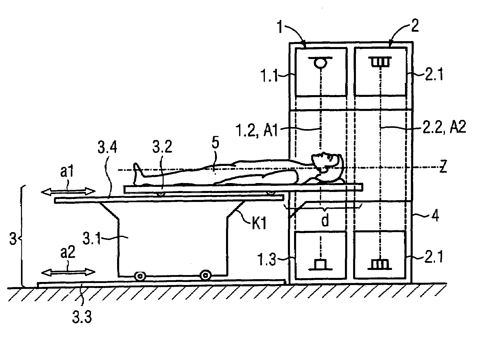
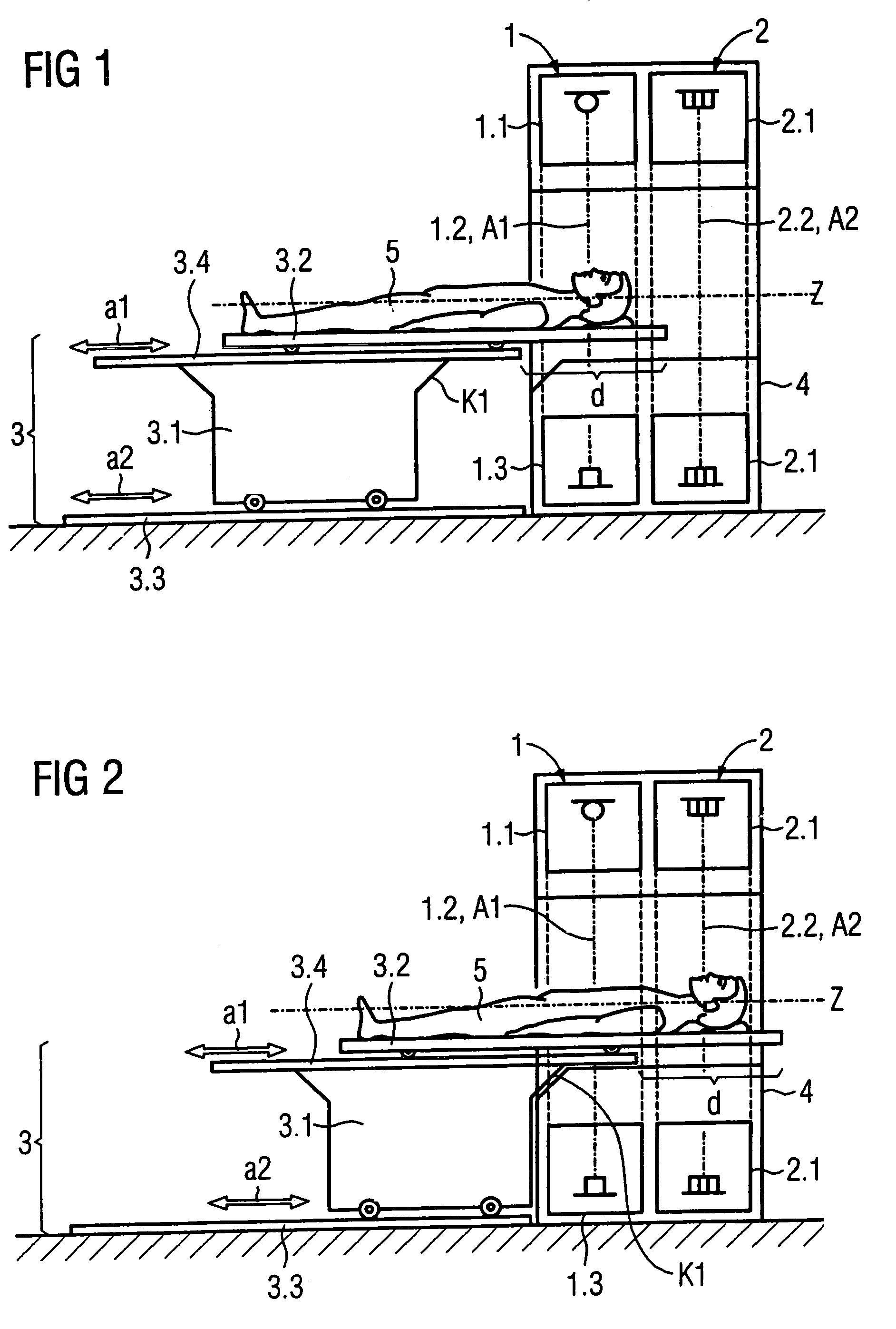
[0020]In a side view, FIG. 1 shows an inventive tomography apparatus with two acquisition systems 1, 2 arranged one after the other in the displacement directions a1, a2, and a support device 3 (which can be displaced in the displacement directions a1, a2) in a first acquisition position A1 relative to the first acquisition system 1. In the shown example the first acquisition system is a CT acquisition system 1 and the second acquisition system is a PET acquisition system 2. The support device has a base 3.1 that can be displaced on rails 3.3 relative to the floor and a support plate 3.2 (that can be displaced relative to the base 3.1 and likewise supported on rails 3.4 in this example) for supporting a subject, in this case a patient 5.

[0021]The CT acquisition system 1 has an x-ray radiator 1.1 and a CT detector 1.3 mounted opposite one another on a rotary frame (not shown) such that, in operation of the CT acquisition system 1, an x-ray beam emanating from a focus of the x-ray rad...


PUM

PropertyMeasurementUnit
weightaaaaaaaaaa
displacementaaaaaaaaaa
PETaaaaaaaaaa

Abstract

A tomography apparatus that has a support device that can be displaced in a displacement direction for supporting a subject, and at least two acquisition systems disposed in succession in the displacement direction of the support device. The support device has a base that can be displaced relative to the floor and a support plate that can be displaced in the displacement direction relative to the base, such that data acquisitions at respective acquisition positions in the respective acquisition systems under essentially identical acquisition conditions are possible in a simple manner.

Description

BACKGROUND OF THE INVENTION[0001]1. Field of the Invention[0002]The present invention concerns a tomography apparatus of the type having a support device (that can be moved in a displacement direction) for supporting a subject and with two acquisition systems disposed in succession in the displacement direction of the support device.[0003]2. Description of the Prior Art[0004]A dual modality tomography apparatus with a support device for a patient and with two acquisition systems (namely a computer tomography (CT) acquisition system and a positron emission tomography (PET) acquisition system) disposed one after the other in the displacement direction is known from U.S. Pat. No. 6,490,476. The support device has a support plate that can be moved relative to the base so that the patient can be shifted between the two acquisition systems. The image data acquired with the respective acquisition systems contain various types of image information and are geometrically fused with one anothe...

Claims


Application Information

Patent Timeline
Patent Type & Authority Patents(United States)
IPC IPC(8): G21K1/12A61B6/04G01T1/164G01N23/04
CPCA61B6/032A61B6/04A61B6/463A61B6/4417A61B8/5238A61B6/5235A61B8/13
Inventor KRONER, HANS-JURGENLOSER, MICHAEL
Owner SIEMENS AG
Why Eureka
Try Eureka