Vibrating device for exercise equipment

a technology of vibration and exercise equipment, applied in the field of vibration exercise equipment, can solve the problems of unsatisfactory shaking of the entire person, complex apparatus, heavy weight, etc., and achieve the effect of reducing the vibration of the frame and maintaining the tension in the member

Active Publication Date: 2007-11-13
CHARNITSKI RICHARD
View PDF23 Cites 33 Cited by
  • Summary
  • Abstract
  • Description
  • Claims
  • Application Information

AI Technical Summary

Benefits of technology

[0004]Briefly described, an oscillating pulley is provided that rotates about its own axis as it encircles another axis, with a motor driving the rotation about both axes, and with a flexible tension member, such as a rope, causing the pulley to further rotate about one axis.
[0006]In further variations of these embodiments the oscillating surface can take the form of a sprocket driving a chain or a belt. But the preferred version uses a pulley engaging a rope or cable. Another variation has the circular oscillating surface encircling the first axis, and if so a bearing is advantageously, but optionally interposed between the oscillating surface the first and second axes to facilitate relative rotational rotation of the oscillating surface about one of the first and second axes.
[0012]There is also provided a method for providing exercise to a user of an exercising device having a flexible tension member connected to a user interface that is connected to a mechanism for generating a resistive force which is overcome by the user to obtain exercise. The method includes wrapping a flexible tension member around part of a circular oscillating surface which is free to rotate about a central axis of that surface, and which is simultaneously rotated about another eccentric axis, causing the tension member to oscillate.
[0014]In a most preferred embodiment there is provided a flexible tension member forming a continuous loop which encircles a driving surface on a sprocket that rotated about two axes to cause the sprocket and tension member to oscillate. At least one, and preferably two hand grips are fastened to the tension member. At least one, and preferably foot rests are also fastened to the tension member, one below hand grip, with the loop being generally vertically oriented to form a climbing exercise device. A tension pulley can optionally engage the tension member to maintain the tension in the member, and advantageously a tension sprocket is used as the tension member advantageously comprises a chain. Most preferably, the tension member has two bars interposed in the continuous loop with the bars arranged substantially parallel, and the hand grips and foot rests fastened to the bars. A resistance device also engages the flexible tension member to provide resistance, while the oscillating driving surface provides vibrational or oscillating motion to the hand grips and foot rests. Resiliently mounting the motor to a frame of the exercise device helps isolate the vibration to the flexible tension member. More generally, interposing one of a vibration isolator or damper between the oscillating surface and a frame of the exercise device is preferably, but optionally used to reduce vibration of the frame.

Problems solved by technology

But these vibrating platforms require lifting the entire weight of the user, thus requiring heavier equipment and stronger motors causing the vibration.
Further, a vibrating platform shakes the entire person, including the joints and muscles not undergoing the longer expansion and contraction.
Shaking an entire person is undesirable.
The prior art has devised various ways to use a vibrating platform and help reduce shaking an entire person, but the resulting apparatus is complex and heavy.

Method used


Image

  • Vibrating device for exercise equipment
  • Vibrating device for exercise equipment
  • Vibrating device for exercise equipment

Examples


Embodiment Construction

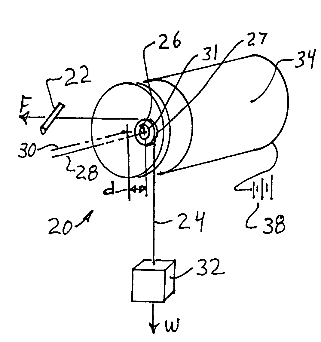
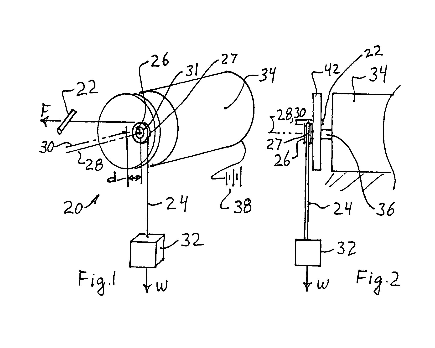
[0045]Referring to FIGS. 1-2, an exercise device 20 is shown which has a user engaging device 22, which for ease of reference and without limiting the invention will be often referred to herein as a handle, although various engaging devices could be used. A person using the device 20 to exercise exerts a force F on the handle 22 using the person's legs, arms, torso, or other body part the muscles of which are to be exercised. The handle 22 is connected to a driven member 24. The driven member 24 advantageously, but optionally comprises a flexible tension member 24, such as a rope, wire, cable, chain or belt. For convenience the flexible tension member 24 will often be referred to as a cable, but is not limited to such.

[0046]The cable 24 curves at least part way around a curved oscillating surface 26 eccentrically mounted oscillating surface 26. The oscillating surface 26 may take various forms, including sprockets, various pulleys, various belt drives and other rotational devices th...


PUM


Abstract

An exercising device has a flexible tension member connected to a user interface that is connected to a mechanism for generating a resistive force which is overcome by the user moving the user interface to obtain exercise. The exercising device has a driving member rotating about a first axis and a circular oscillating surface rotatably connected to the driving member to circle about the first axis while also rotating about a second substantially parallel axis through the center of the circular oscillating surface. The first and second axes are offset a distance d. The flexible member wraps at least part way around the circular oscillating surface to rotate the oscillating surface as the user interface moves during use of the exercise device. The offset d provides an oscillatory motion to the user interface to increase the effectiveness of the exercise.

Description

BACKGROUND OF THE INVENTION[0001]This application relates to vibrating exercise devices.[0002]Exercise devices are known which cause a user's muscles to travel between two positions during which the user's muscles expand and contract. The resistance is typically provided by the effect of gravity on weights, or by a spring resistance or motors. Beginning in the 1980's Russian patents began to disclose vibrating platforms on which a person stood during exercise, with the vibrating platform superimposing a vibration that caused the user's muscles to expand and contract short distances arising from the vibration while simultaneously undergoing the longer expansion and contraction arising from the normal exercise. But these vibrating platforms require lifting the entire weight of the user, thus requiring heavier equipment and stronger motors causing the vibration. There is thus a need for a simpler way to provide a vibrational force directly to a more specific muscle or muscle groups to ...

Claims


Application Information

Patent Timeline
Patent Type & Authority Patents(United States)
IPC IPC(8): A63B21/002A61H23/00A63B21/00A63B21/075A63B21/22A63B23/035
CPCA63B21/00A63B21/00196A63B21/154A63B21/00069A63B21/00076A63B21/00061A63B21/155A61H23/00A63B23/0355
Inventor CHARNITSKI, RICHARD
Owner CHARNITSKI RICHARD
Why Eureka
Try Eureka