
Microelectronic workpiece processing tool including a processing reactor having a paddle assembly for agitation of a processing fluid proximate to the workpiece

Inactive Publication Date: 2007-11-13
SEMITOOL INC
View PDF71 Cites 20 Cited by
  • Summary
  • Abstract
  • Description
  • Claims
  • Application Information

AI Technical Summary

Benefits of technology

[0014]In accordance with one independent aspect of the present invention an integrated tool for processing a workpiece is set forth including at least one processing station. The processing station comprises a bowl assembly, and a head assembly for receiving a workpiece and orienting the workpiece within the bowl assembly. The processing station further includes a paddle assembly, which includes a paddle adapted for movement relative to the workpiece when the workpiece is disposed on the head assembly within the bowl assembly. The processing station further comprises a fluid inlet for supplying processing fluid to the bowl assembly, and at least one fluid path for adjusting the position of the leve

Problems solved by technology

There are instances, however, in which spinning a workpiece relative to the processing fluid is undesirable.
For example, rotation of the workpiece may be undesirable when electroplating certain materials onto a workpiece where the deposited material must be uniformly aligned in a particular magnetically polarized direction.
A continuously changing orientation of the magnetic field would disrupt the formation of the desired magnetically uniform deposition.
In these instances, concurrent processing of the entire portion of the workpiece to be processed can produce undesirable or incomplete results.
Effectively the processing fluid associated with the electroetch process is then unavoidably present throughout the processing chamber.
The presence of processing fluid throughout the processing chamber may preclude the use of the same processing chamber for use in a subsequent processing step, especially where a different processing fluid is used.
The processing fluid present from the preceding step may provide a source of chemical contamination or may result in the mixing of chemicals, which may produce undesirable results.
Accordingly, under these circumstances, it may be very difficult to use the same processing chamber for other processing steps.
This results in an increased cost for the tool as well as an increase in the required tool footprint.
The risk of cross contamination of the chemistries between each of the steps renders the co-development of these differing approaches counter-intuitive.
As a result, the use of a paddle assembly within a given processing chamber has been effectively limited to a single processing step or purpose.

Method used


Image

  • Microelectronic workpiece processing tool including a processing reactor having a paddle assembly for agitation of a processing fluid proximate to the workpiece
  • Microelectronic workpiece processing tool including a processing reactor having a paddle assembly for agitation of a processing fluid proximate to the workpiece
  • Microelectronic workpiece processing tool including a processing reactor having a paddle assembly for agitation of a processing fluid proximate to the workpiece

Examples


Embodiment Construction

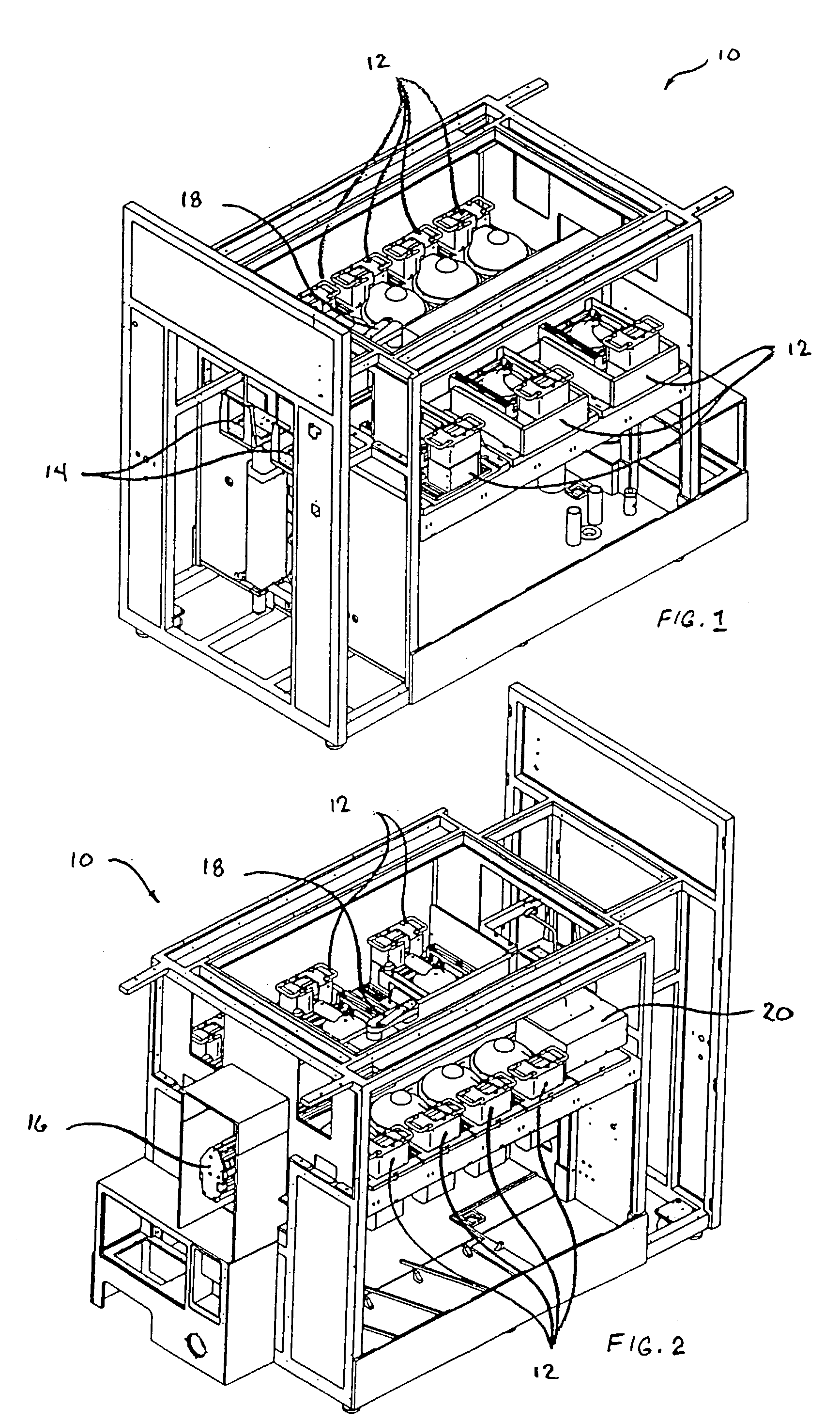
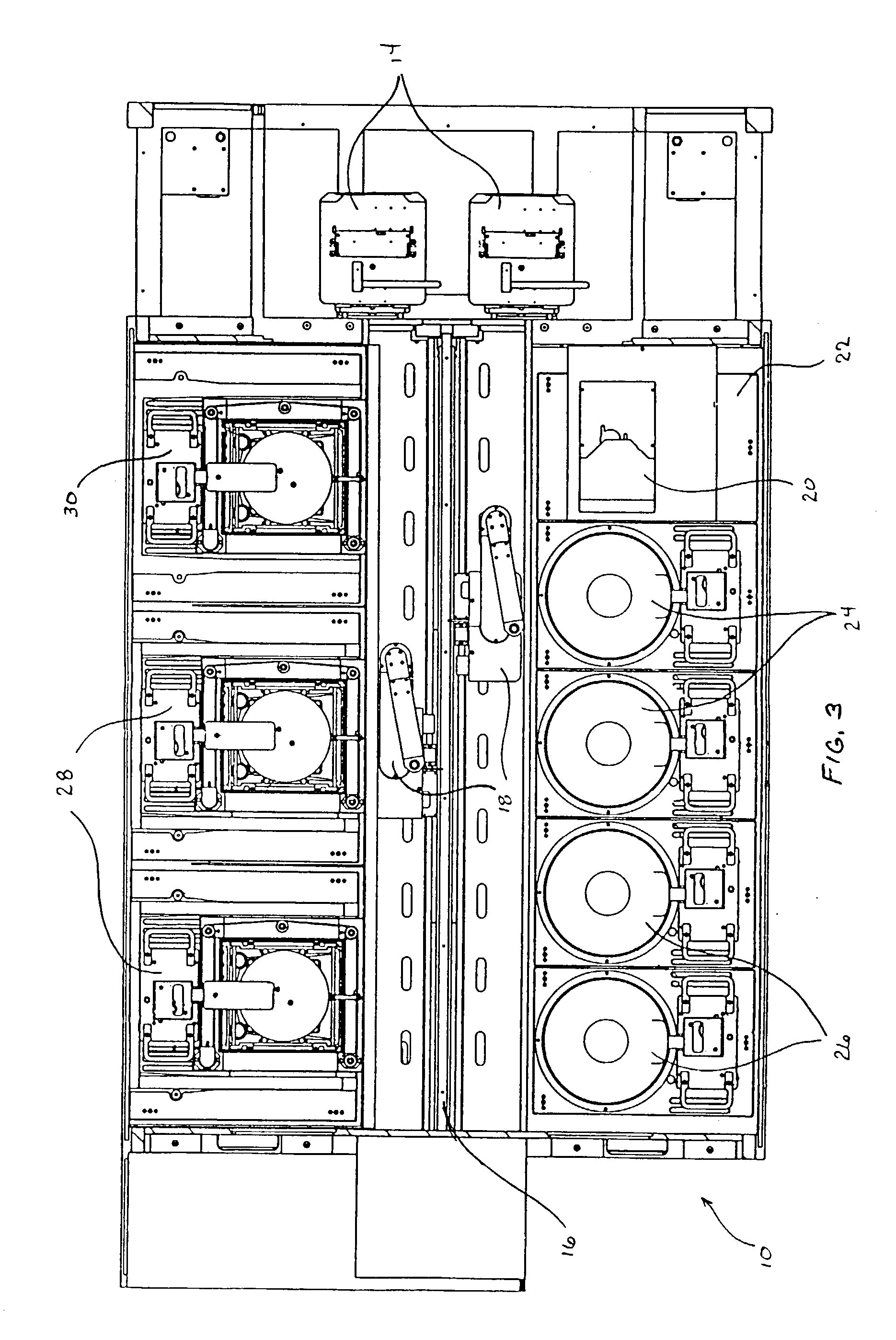
[0047]FIGS. 1 and 2 illustrate corresponding isometric views of an integrated processing tool 10, shown with several panels removed. The integrated processing tool 10 incorporates multiple processing stations 12. Workpieces are generally received within the integrated processing tool 10, via cassettes containing one or more workpieces. The cassettes containing the workpieces enter and exit the integrated processing tool 10, via a door in the side of the integrated processing tool 10, where the cassettes are received by a pair of lift / tilt mechanisms 14. The lift / tilt mechanisms 14 position and orient the cassettes to provide access to the individual workpieces contained therein. A linear conveyor system 16 receives the individual workpieces and relays them to the various processing stations 12.

[0048]Additional details in connection with the lift / tilt mechanism 14 and the linear conveyor system 16 are provided in connection with U.S. patent application Ser. No. 08 / 990,107, now U.S. P...


PUM

PropertyMeasurementUnit
Widthaaaaaaaaaa

Abstract

An integrated tool is provided including at least one workpiece processing station having a paddle assembly. In accordance with another independent aspect of the present invention, the workpiece processing station is adapted for adjusting the level of the processing fluid relative to a workpiece, wherein the portion of the workpiece to be processed and possibly the paddle is selectively immersed within the processing fluid. In accordance with a further independent aspect of the present invention, a paddle is provided for use proximate to a workpiece in a workpiece processing station. The paddle includes a one or more sets of delivery ports and one or more sets of fluid recovery ports. In at least one embodiment, the paddle provides for agitation of a processing fluid proximate to the surface of the workpiece. In at least another embodiment, the paddle provides for the delivery and / or recovery of one or more fluids to the portion of the workpiece to be processed. One aspect of the present invention enables the fluids supplied to the workpiece by the paddle to be limited to the space located between the workpiece and the paddle, thus avoiding mixing of these fluids with the processing fluid located within the bowl assembly not supplied by the paddle.

Description

CROSS-REFERENCE TO RELATED APPLICATIONS[0001]This application is a continuation of U.S. patent application Ser. No. 09 / 476,526, now U.S. Pat. No. 6,547,937, filed Jan. 3, 2000, and titled “MICROELECTRONIC WORKPIECE PROCESSING TOOL INCLUDING A PROCESSING REACTOR HAVING A PADDLE ASSEMBLY FOR AGITATION OF A PROCESSING FLUID PROXIMATE TO THE WORKPIECE”.STATEMENT REGARDING FEDERALLY SPONSORED RESEARCH OR DEVELOPMENT[0002]Not ApplicableBACKGROUND OF THE INVENTION[0003]The present invention generally relates to an apparatus for processing a microelectronic workpiece. More particularly, the present invention is directed to a microelectronic workpiece processing tool having a reactor that includes a paddle assembly, which moves relative to the workpiece for facilitating the processing of a microelectronic workpiece. For purposes of the present application, a microelectronic workpiece is defined to include a substrate upon which microelectronic circuits or components, data storage elements or...

Claims


Application Information

Patent Timeline
IPC IPC(8): C25F3/12C25B9/12C25D5/00C25D7/00C25D7/12C25D17/00C25D21/10H01L21/00
CPCC25D5/08C25D21/10H01L21/67005H01L21/67023C25D17/001H01L21/67086H01L21/6723C25D17/007H01L21/67057C25D7/123
Inventor OBERLITNER, THOMAS H.HANSON, KYLE M.
Owner SEMITOOL INC
Learn More