Method of and apparatus for determining tire shapes
a technology of displacement gage and tire shape, which is applied in the direction of measurement devices, instruments, vehicle components, etc., can solve the problems of lowering determination accuracy, affecting the accuracy of tire shape determination, so as to reduce the weight of the apparatus and improve the effect of determination accuracy
- Summary
- Abstract
- Description
- Claims
- Application Information
AI Technical Summary
Benefits of technology
Problems solved by technology
Method used
Image
Examples
first embodiment
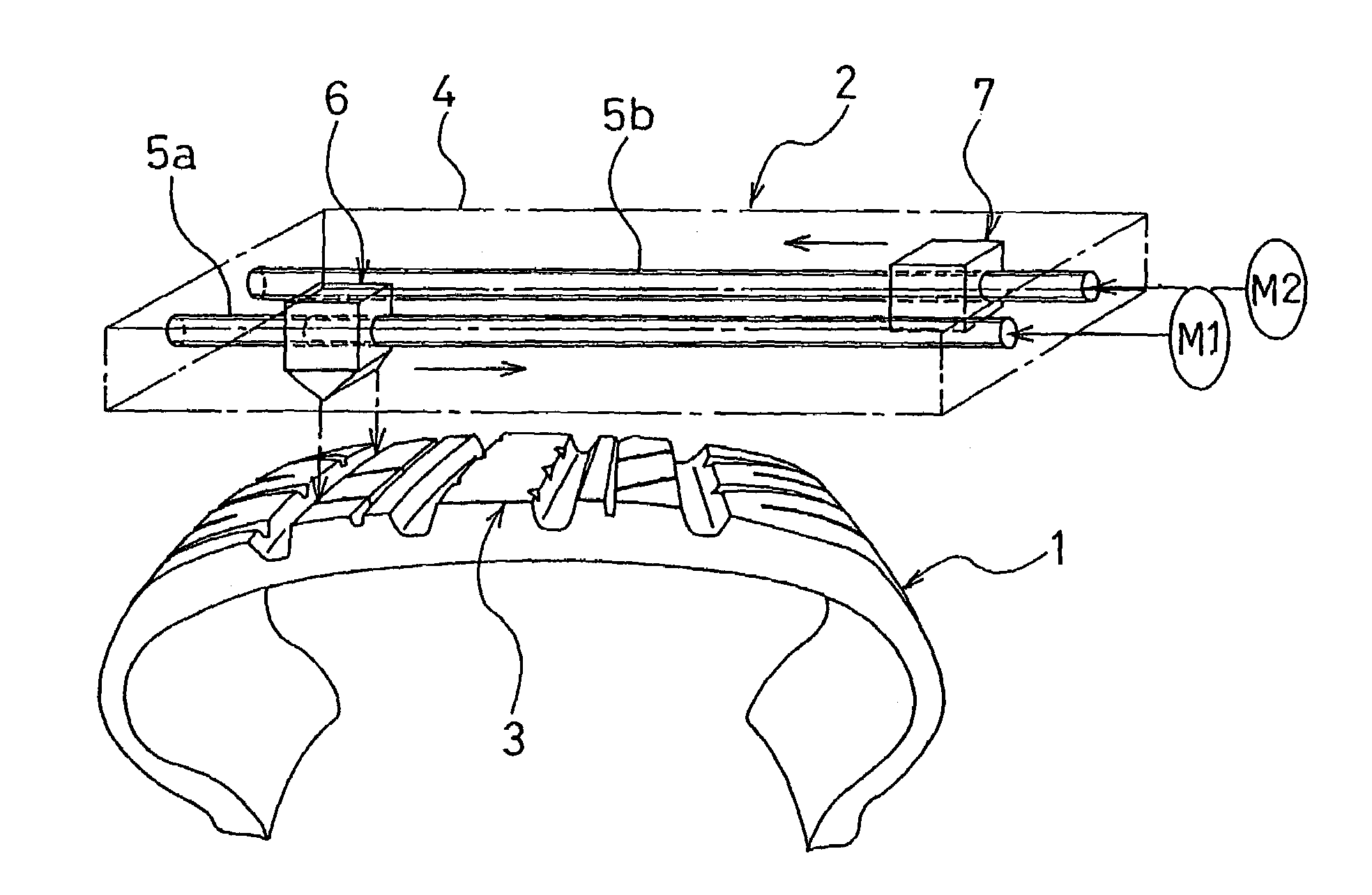
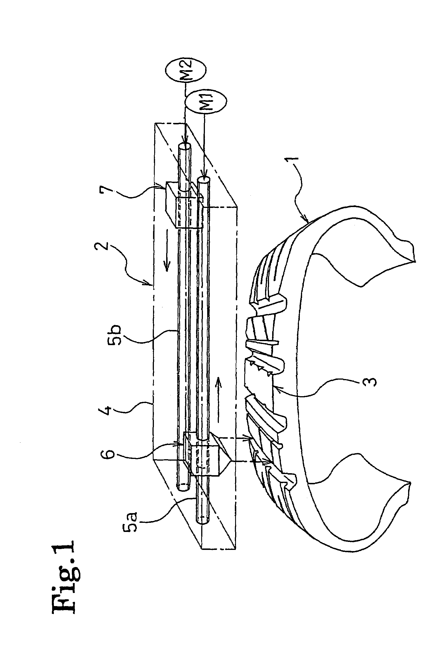
[0016]FIG. 1 shows an apparatus for determining tire shapes according to the present invention. In FIG. 1, the numeral 1 denotes a tire to be measured, and 2 denotes the portable determination apparatus disposed in proximity to a tread portion 3 of the tire 1.
[0017]This determination apparatus 2 has a structure in which two ball screws 5a and 5b are rotatably arranged in parallel with each other in a base member 4 shaped like a box. The ball screw 5a holds an optical displacement gage 6, including a laser light source and a sensor for receiving laser light reflected from a tire surface, so that the optical displacement gage 6 can freely move along a predetermined scanning direction. Meanwhile, the ball screw 5b holds a weight 7, having substantially the same mass as the optical displacement gage 6, so that the weight 7 can freely move along the same scanning direction as that of the optical displacement gage 6. These ball screws 5a and 5b are configured to rotate each in an arbitrar...
second embodiment
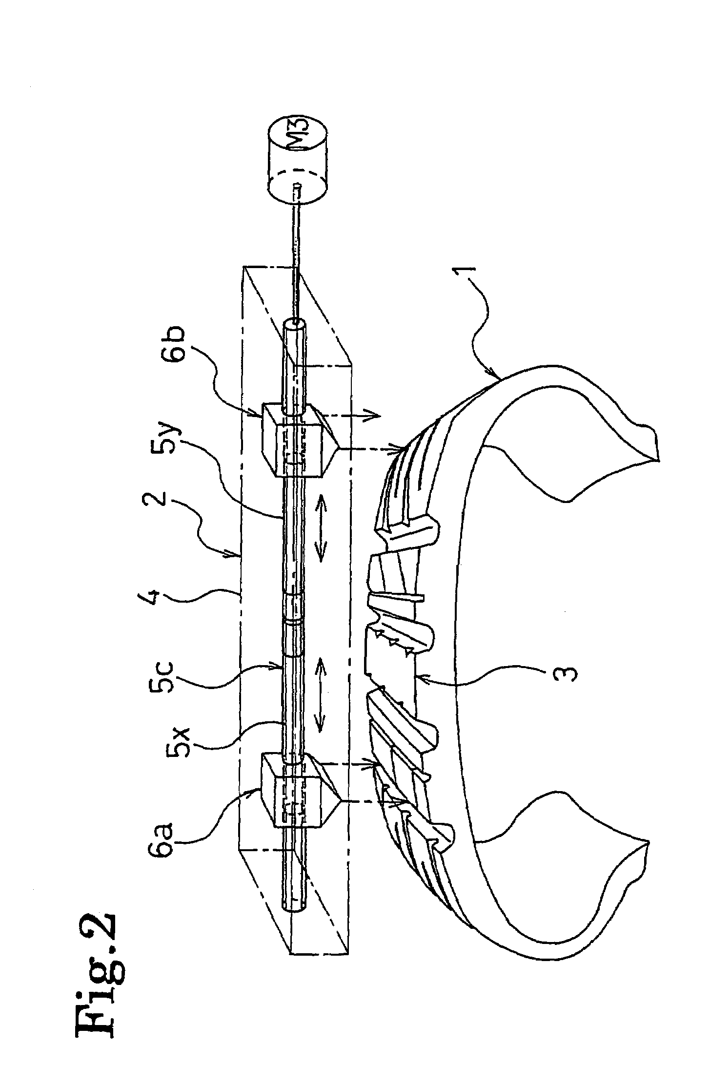
[0023]FIG. 2 shows another apparatus for determining tire shapes according to the present invention. In FIG. 2, a determination apparatus 2 has a structure in which one ball screw 5c is rotatably arranged in a base member 4 shaped like a box. The ball screw 5c holds a pair of optical displacement gages 6a and 6b so that they can move along a predetermined scanning direction. The optical displacement gages 6a and 6b have substantially the same masses and each include a laser light source and a sensor for receiving laser light reflected from a tire surface. More specifically, screw parts 5x and 5y with different thread directions from each other are formed in the ball screw 5c, bordering a central portion of the ball screw 5c in its longitudinal direction. The optical displacement gage 6a is held within a screw part 5x area, while the optical displacement gage 6b is held within a screw part 5y area. The ball screw 5c is configured to rotate in an arbitrary direction, with a servomotor...
PUM
 Abstract
Description
Claims
Application Information
 - R&D
- Intellectual Property
- Life Sciences
- Materials
- Tech Scout
- Unparalleled Data Quality
- Higher Quality Content
- 60% Fewer Hallucinations
Browse by: Latest US Patents, China's latest patents, Technical Efficacy Thesaurus, Application Domain, Technology Topic, Popular Technical Reports.
© 2025 PatSnap. All rights reserved.Legal|Privacy policy|Modern Slavery Act Transparency Statement|Sitemap|About US| Contact US: help@patsnap.com


