Optical LAN device

a technology of optical lan and optical lan, applied in the field of optical lan devices, can solve problems such as network crash and network crash, and achieve the effect of suppressing network crash

Inactive Publication Date: 2007-11-13
PACIFIC INDUSTRIAL CO LTD
View PDF6 Cites 21 Cited by
  • Summary
  • Abstract
  • Description
  • Claims
  • Application Information

AI Technical Summary

Benefits of technology

[0007]Accordingly, it is an objective of the present invention to provide an optical LAN device capable of suppressing a network crash caused by a failure of a slave node maintaining a corresponding light sending portion in a turned on state.

Problems solved by technology

However, if any one of the slave nodes fails, the optical signal cannot be passed to the slave node subsequent to the failed slave node, leading to a network crash.
This prevents the slave nodes subsequent to the failed slave node and the master node from reading required information from the signal transmitted through the network, resulting in a network crash.

Method used


Image

  • Optical LAN device
  • Optical LAN device
  • Optical LAN device

Examples


Embodiment Construction

[0016]An embodiment of the present invention will now be described with reference to the attached drawings.

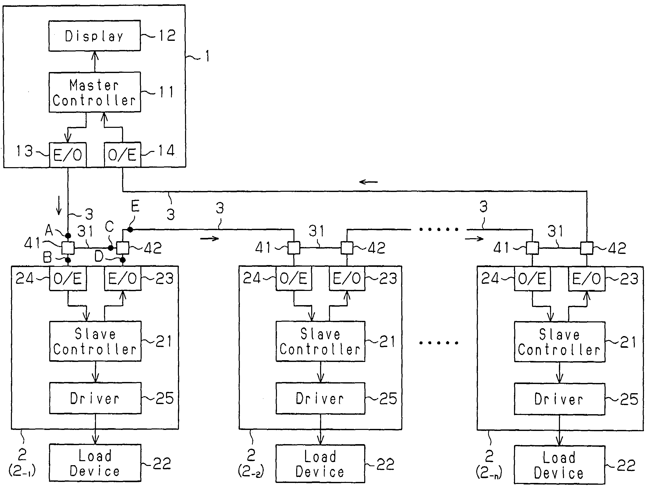
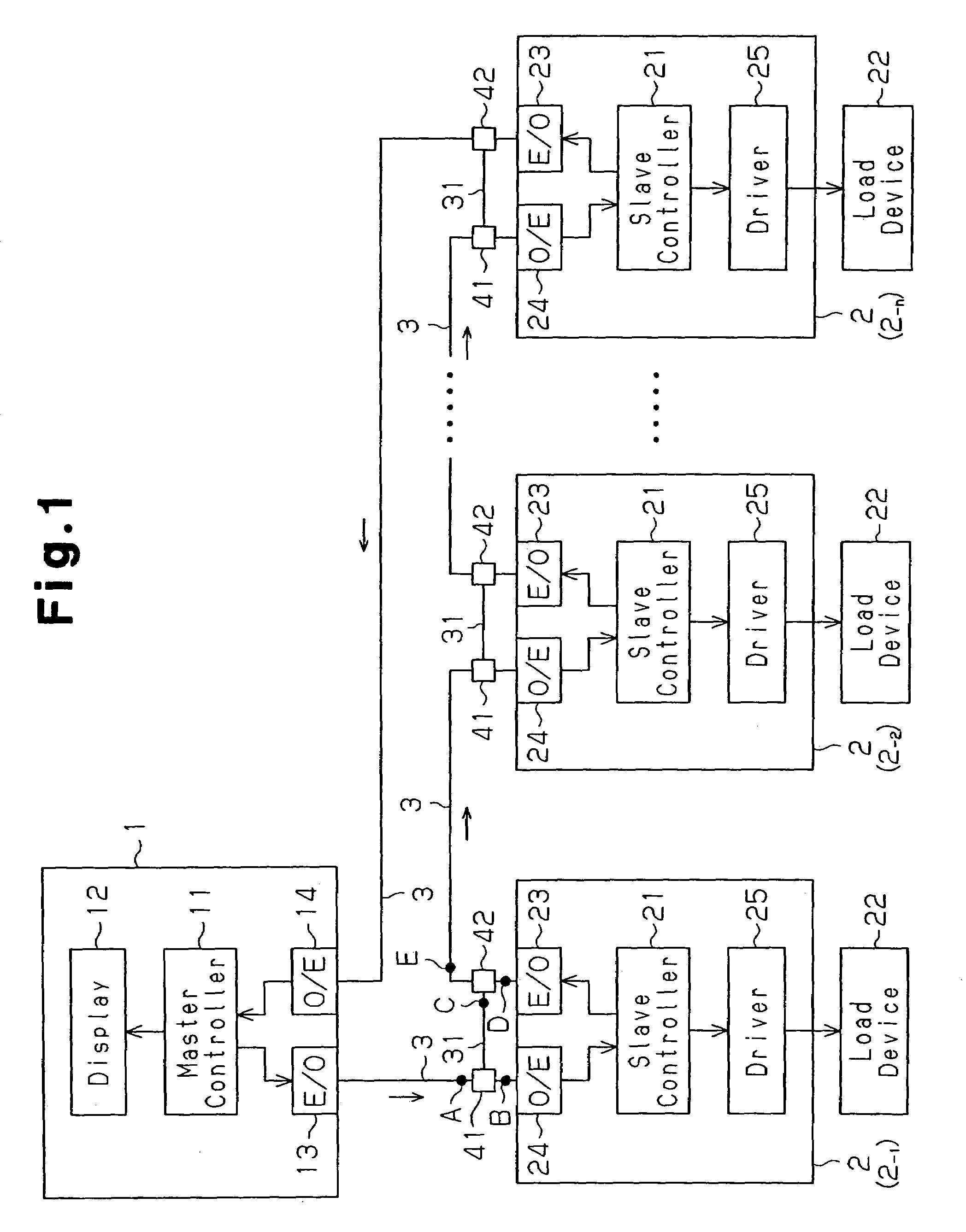
[0017]As illustrated in FIG. 1, an optical LAN device according to the present invention is a ring type, which is preferably applied to vehicles. The ring type optical LAN device includes a master node 1 and a plurality of slave nodes 2, or first to n-th slave nodes 2-1 to 2-n. The master node 1 and each of the slave nodes 2 are interconnected by an optical fiber cable 3, such that a ring type network is established.

[0018]The master node 1 is installed in, for example, an instrument panel of a vehicle (not illustrated). The master node 1 includes a controller (a master controller) 11, which is formed by a microcomputer or the like. The master controller 11 includes, for example, a central processing unit (CPU), a read only memory (ROM), and a random access memory (RAM). A display 12 serving as an annunciator is connected to the master controller 11. The display 12 is exposed on...


PUM


Abstract

An ring type optical LAN device includes a master node and a plurality of slave nodes that are interconnected by an optical fiber cable. A plurality of optical bypass transmission lines are provided in correspondence with each one of the slave nodes. Each of the optical bypass transmission lines bypasses the corresponding one of the slave nodes. Each slave node includes an E / O converter and an optical cutoff circuit. Each of the E / O converters is controlled to flash for generating an optical signal, which is transmitted to a network. When any one of the slave nodes fails such that the corresponding E / O converter is maintained in a turned on state, the associated optical cutoff circuit forcibly switches the E / O converter to a turned off state. This suppresses a network crash caused by the failure maintaining the E / O converter in the turned on state.

Description

BACKGROUND OF THE INVENTION[0001]The present invention relates to optical LAN devices including a master node and a plurality of slave nodes that are interconnected by an optical fiber cable for configuring a network, and, more particularly, to techniques for suppressing a network crash due to failure caused in the slave nodes.[0002]Typically, a ring type optical LAN device includes a master node and a plurality of slave nodes that are interconnected by an optical-fiber cable for configuring a network. In this device, an optical signal is sent from the master node to the network, circulated through the slave nodes, and returned to the master node. However, if any one of the slave nodes fails, the optical signal cannot be passed to the slave node subsequent to the failed slave node, leading to a network crash.[0003]To solve this problem, Japanese Laid-Open Patent Publication No. 11-313098 describes a technique for preventing a network crash even if part of the slave nodes fails. More...

Claims


Application Information

Patent Timeline
Patent Type & Authority Patents(United States)
IPC IPC(8): H04B10/20H04B10/03H04B10/07H04B10/077H04B10/27H04B10/275H04B10/29H04J14/00H04L12/24H04L12/437
CPCH04L12/437H04L41/0803
Inventor OKUBO, YOUICHIKATOU, MICHIYAKAWASE, SHINICHI
Owner PACIFIC INDUSTRIAL CO LTD
Why Eureka
Try Eureka