
Valve assembly and refueling sensor

a valve and sensor technology, applied in the field of fuel systems, can solve the problems of affecting the integrity of the wires and their connections, affecting the pressure of the fuel tank, and affecting the operation of the valve, so as to facilitate the pressure and leakage testing of the fuel tank, and facilitate the effect of rapid venting and simple design

Inactive Publication Date: 2007-11-20
TI GRP AUTOMOTIVE SYST LLC
View PDF6 Cites 22 Cited by
  • Summary
  • Abstract
  • Description
  • Claims
  • Application Information

AI Technical Summary

Benefits of technology

This solution provides accurate detection of refueling events, facilitates fuel tank pressure and leak testing, enables electronic fill level control, and ensures rapid venting of fuel vapors, while being simple in design and economical to manufacture and assemble, with a long service life.

Problems solved by technology

Additionally, fuel fill caps can be lost or the vehicle may be operated with the fill cap removed, the fill door may become stuck in an open position at least temporarily, and the integrity of the wires and their connections may become compromised.

Method used


Image

  • Valve assembly and refueling sensor
  • Valve assembly and refueling sensor
  • Valve assembly and refueling sensor

Examples


Embodiment Construction

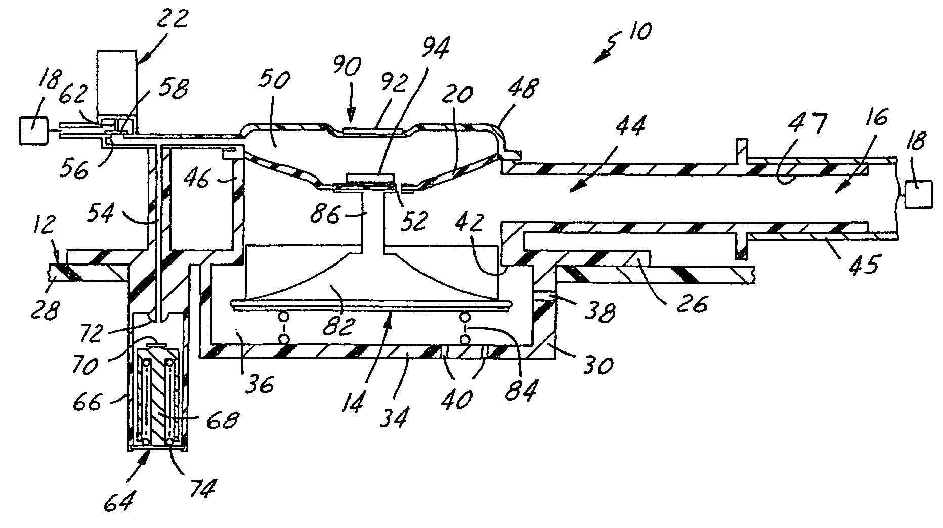
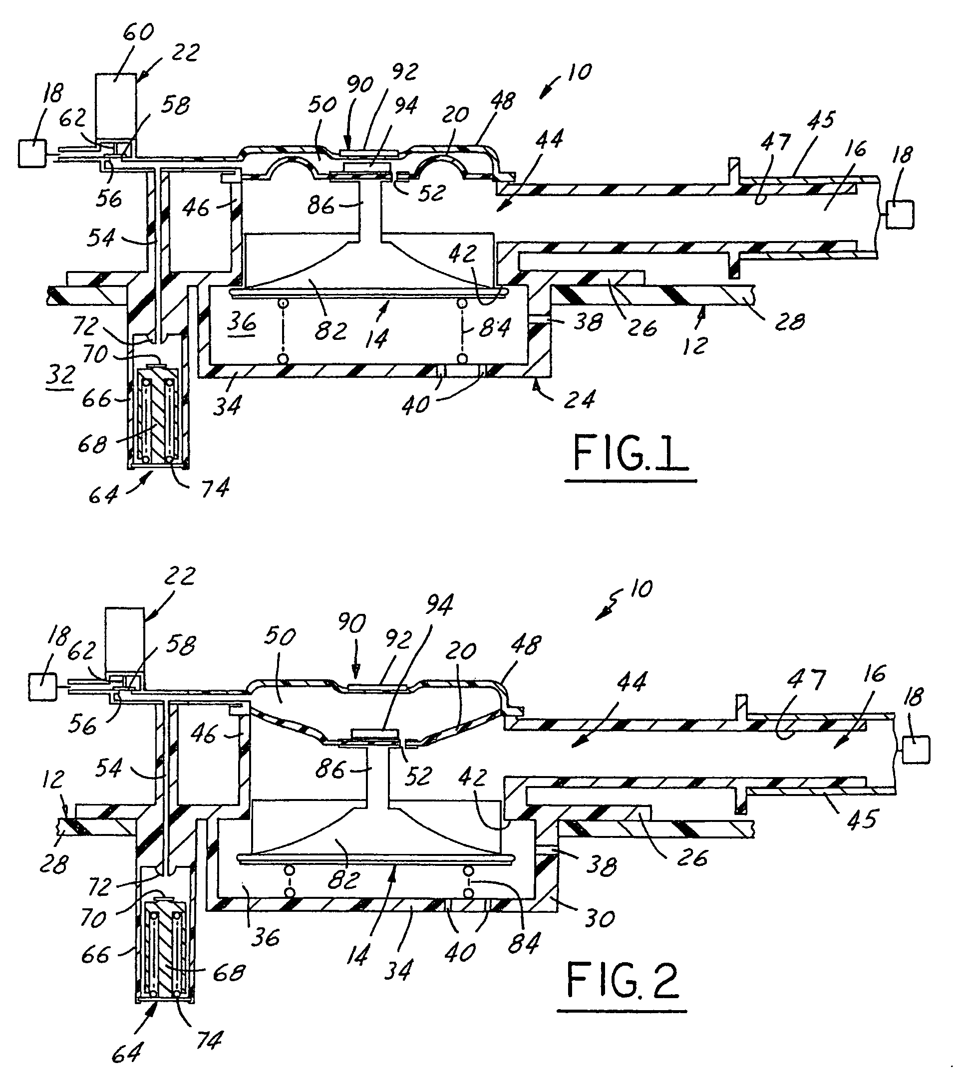
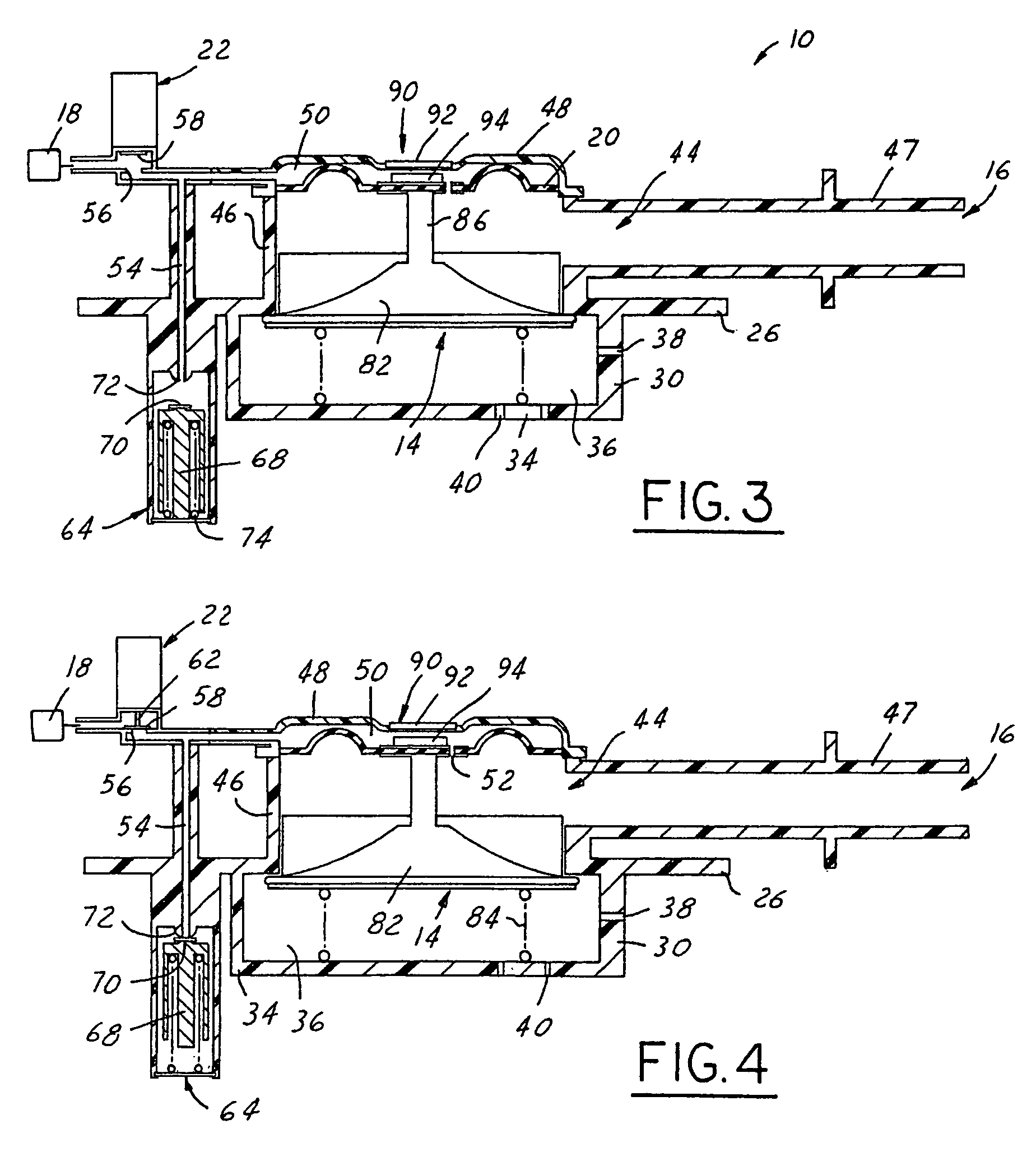
[0016]Referring in more detail to the drawings, FIGS. 1-4 illustrate one presently preferred embodiment of a valve assembly 10 such as for a vehicle fuel system that includes a refueling sensor to determine when fuel is being added to a fuel tank 12 of the fuel system. The assembly 10 includes a vent valve 14 that selectively opens a vent outlet 16 to permit fuel vapor within the fuel tank 12 to be vented from the fuel tank 12, such as to a fuel vapor canister 18 or other fuel vapor receiver. The valve 14 is preferably coupled to a pressure responsive member 20, such as a flexible diaphragm, and is movable in response to a pressure signal applied to the pressure responsive member 20. Desirably, an electronic valve 22 controls application of a pressure signal to the pressure responsive member 20 to thereby control movement of the pressure responsive member 20 and hence, of the valve 14. A sensor, switch or other device may be associated with the valve 14 or the pressure responsive me...


PUM

PropertyMeasurementUnit
pressure responsiveaaaaaaaaaa
pressureaaaaaaaaaa
threshold valueaaaaaaaaaa

Abstract

A valve assembly includes a housing having a valve seat defining at least part of a vent passage, a pressure responsive member carried by the housing and defining at least part of a pressure chamber, and a valve carried by the housing and having a closure movable relative to the valve seat between an open position permitting fluid flow through the vent passage and a closed position at least substantially restricting fluid flow through the vent passage. The closure is moved by the pressure responsive member in response to changes in pressure in the pressure chamber. A control passage communicates at one end with a pressure source and at its other end with the pressure chamber and an electrically operated valve is movable from a first position permitting a pressure signal to develop within the pressure chamber and a second position permitting pressure within the pressure chamber to vent.

Description

FIELD OF THE INVENTION[0001]The present invention relates generally to fuel systems and more particularly to a sensor and valve for detecting a refueling event and venting fuel vapors from a fuel tank.BACKGROUND OF THE INVENTION[0002]Environmental concerns and governmental regulations require reduced emissions to the atmosphere of volatile hydrocarbon fuel vapors. One source of hydrocarbon fuel vapors is the fuel tanks of vehicles using gasoline or other hydrocarbon fuels. Fuel vapor can escape to the atmosphere during the filling of the tanks and usually even after the tanks are filled. The use of an onboard vapor recovery system to remove excess fuel vapor from the fuel tank is one solution to the problem. Typically, a canister with activated charcoal therein receives fuel vapors through a valve assembly mounted to the fuel tank. The vapor canister communicates with the intake manifold of a vehicle engine for exhausting fuel vapor from the canister during operation. The valve asse...

Claims


Application Information

Patent Timeline
Patent Type & Authority Patents(United States)
IPC IPC(8): B65B1/30
CPCF02M25/0836B60K2015/03576
Inventor FERRERIA, DAVID M.FORGUE, JOHN R.JOHANSEN, MARK R.
Owner TI GRP AUTOMOTIVE SYST LLC
Learn More