
Check valve apparatus for fuel delivery systems

a technology of fuel delivery system and check valve, which is applied in the direction of functional valve types, machines/engines, liquid fuel feeders, etc., can solve the problems of high cost, high labor intensity, and high cost of the screw machining process required to make the valve seat and poppet valve, so as to reduce the weight and cost of the product, and the process used to mold the rubber tip to the poppet valve is relatively expensive. , the effect of simple design

Inactive Publication Date: 2010-06-01
TI GRP AUTOMOTIVE SYST LLC
View PDF21 Cites 18 Cited by
  • Summary
  • Abstract
  • Description
  • Claims
  • Application Information

AI Technical Summary

Benefits of technology

[0005]At least some of the objects, features and advantages that may be achieved by at least certain embodiments of the invention include providing a check valve apparatus that is readily adaptable to various fluid flow applications including fuel pumps and fuel systems, responsive to rapidly changing fluid pressure conditions, wherein the check valve apparatus yields a reduction in product weight and cost, performs as well or better than conventional designs, and is of relatively simple design and economical manufacture and assembly, is rugged, durable, and reliable, and in service has a long, useful life.

Problems solved by technology

Unfortunately, however, the conventional check valve apparatus has several shortcomings.
First, the screw machining process required to make the valve seat and poppet valve is particularly time-consuming and costly.
Second, brass is a relatively heavy and costly material.
Third, the process used to mold the rubber tip to the poppet valve is relatively expensive.
Fourth, in fuel systems where fuel pump speed adjusts to engine fuel demand, a valve assembly having a brass poppet valve has relatively low responsiveness to rapidly changing fuel pressure and demand conditions such as when a vehicle is accelerating, decelerating, or shifting gears, because of the relatively high mass of a brass poppet valve.

Method used


Image

  • Check valve apparatus for fuel delivery systems
  • Check valve apparatus for fuel delivery systems
  • Check valve apparatus for fuel delivery systems

Examples


Embodiment Construction

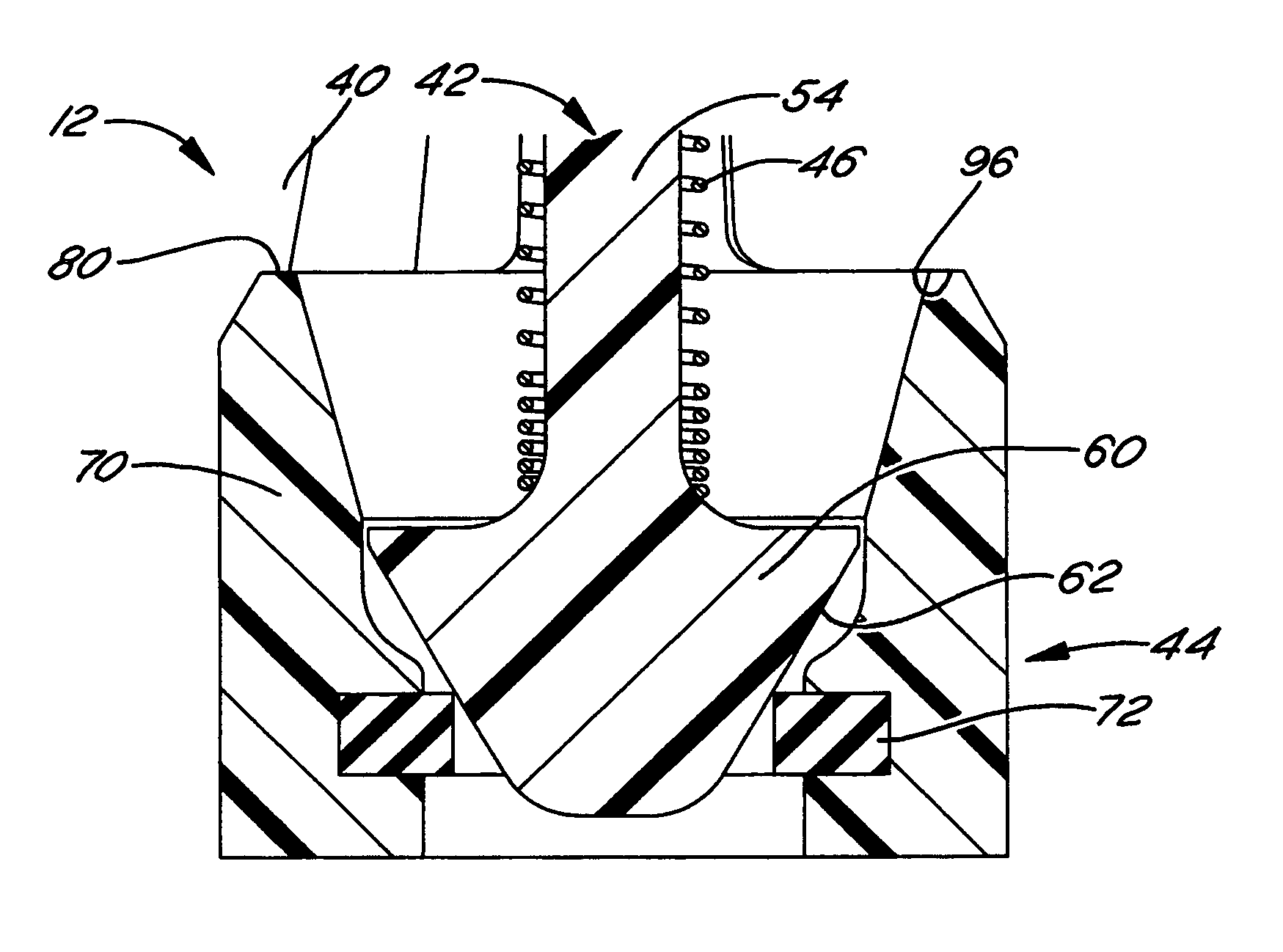
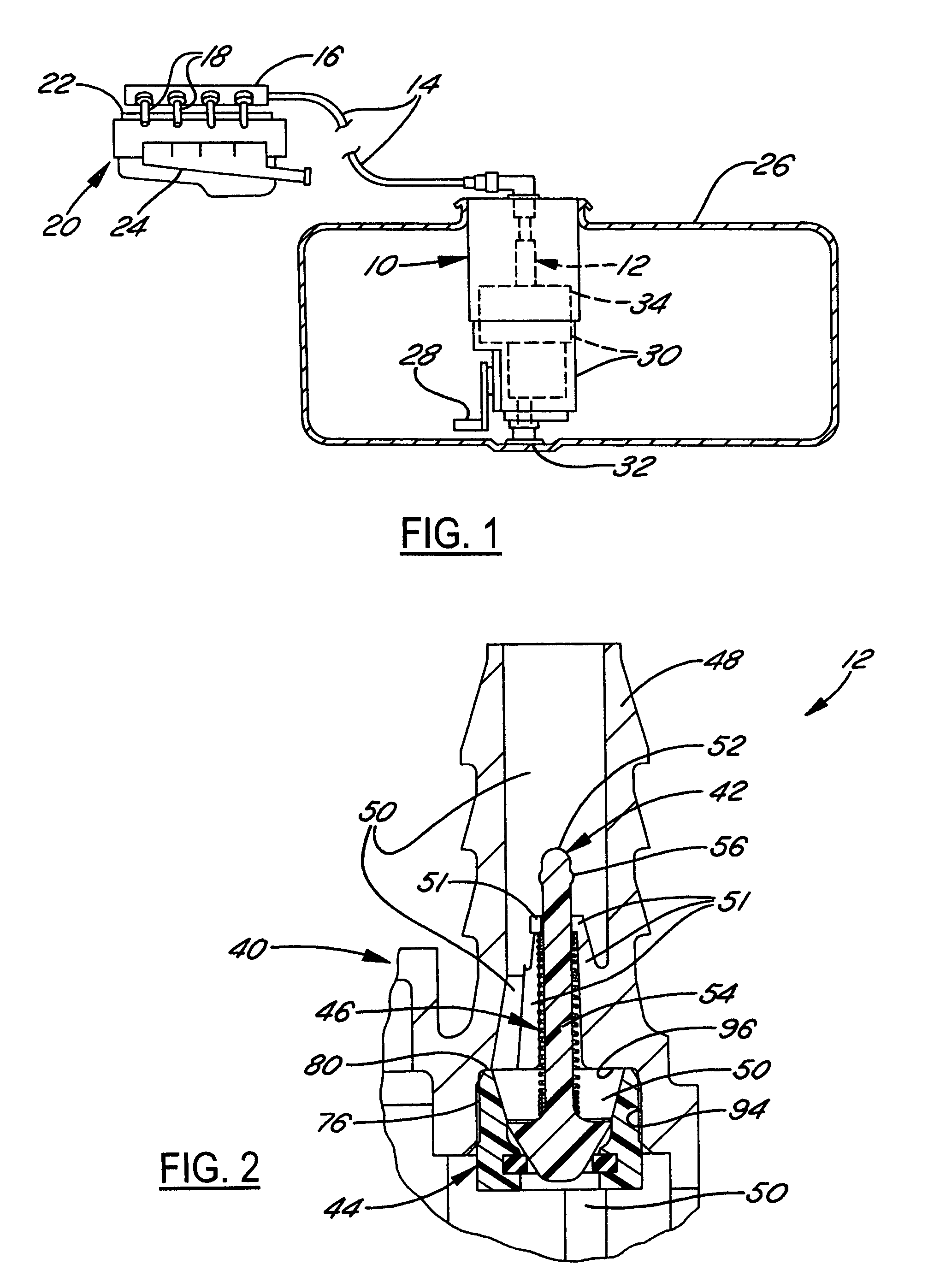
[0016]Referring in detail to the drawings, FIG. 1 illustrates a fuel system having a fuel pump module 10 with an integrated valve assembly 12, according to a preferred exemplary embodiment. The valve assembly 12 is connected by a fuel line 14 to a fuel rail 16 and associated fuel injectors 18 of an internal combustion engine 20 having an air intake manifold 22 and an exhaust manifold 24. The valve assembly 12 functions as a check valve for permitting free flow of fuel from the pump module 10 to the fuel rail 16 as required by the engine when the pump module 10 is operating, and for preventing back-flow of fuel from the fuel rail 16 to the pump module 10 when the engine and pump module 10 are shut off.

[0017]The pump module 10 is mounted in a fuel tank 26 and has a fuel level sensor 28 and a fuel pump 30 with an outlet connected to the valve assembly 12 and an inlet communicating with the bottom of the tank through a fuel filter 32. The pump 30 is driven by an electric motor 34, which...


PUM


Abstract

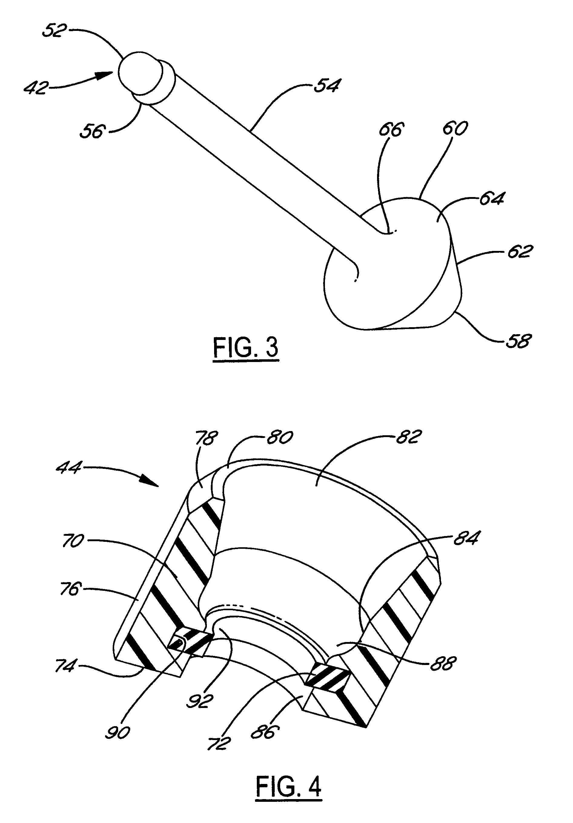
A check valve for a combustion engine fuel system includes a polymeric poppet valve including a valve stem and a valve head that terminates the valve stem. A valve seat is adapted for cooperation with the valve head of the poppet valve, and includes a valve seat body and an elastomeric valve seat seal supported by the valve seat body and adapted for sealing against the valve head of the poppet valve. The check valve is particularly adapted for use with a fuel pump within a fuel system.

Description

FIELD OF THE INVENTION[0001]This invention relates generally to fuel delivery systems, and more particularly to an improved check valve apparatus for a fuel delivery system for an internal combustion engine.BACKGROUND OF THE INVENTION[0002]Fuel delivery systems typically include a fuel pump for delivering fuel under pressure from a fuel tank to an internal combustion engine. A check valve is usually positioned in line between the fuel pump and the engine to prevent back flow of fuel from the engine to the fuel pump when the fuel pump is deactivated. Fuel pressure is thereby maintained at the engine, resulting in reduced start-up time and improved starting of the engine. As depicted in FIG. 8, a conventional check valve apparatus 112 includes a screw-machined brass valve seat 144 and brass poppet valve 142 that has a rubber tip 143 molded thereto for sealing against the valve seat 144.[0003]Unfortunately, however, the conventional check valve apparatus has several shortcomings. First...

Claims


Application Information

Patent Timeline
Patent Type & Authority Patents(United States)
IPC IPC(8): F16K21/04
CPCF02M37/0023F02M37/10Y10T137/7932Y10T137/7933F02M37/00F16K15/00F16K15/06
Inventor DOBLE, CORY J.
Owner TI GRP AUTOMOTIVE SYST LLC
Learn More