Imaging and treatment system

a treatment system and imaging axis technology, applied in the field of imaging and treatment systems, can solve the problems of not being able to allow full axial rotation, and the imaging axis not being parallel to the longitudinal direction of all couches,

Inactive Publication Date: 2007-11-20
EIN GAL MOSHE
View PDF13 Cites 36 Cited by
  • Summary
  • Abstract
  • Description
  • Claims
  • Application Information

AI Technical Summary

Problems solved by technology

The construction does not typically allow full axial rotations but provides some limited rotations about a longitudinal axis through the patient (i.e., partial roll) and a vertical axis not through the patient (i.e., partial azimuth).
However, the imaging device typically moves independently of the gantry of the treatment device.
However, the prior art has the disadvantage of the imaging axis not being parallel to the couch longitudinal direction for all couch angles.

Method used


Image

  • Imaging and treatment system
  • Imaging and treatment system
  • Imaging and treatment system

Examples


Embodiment Construction

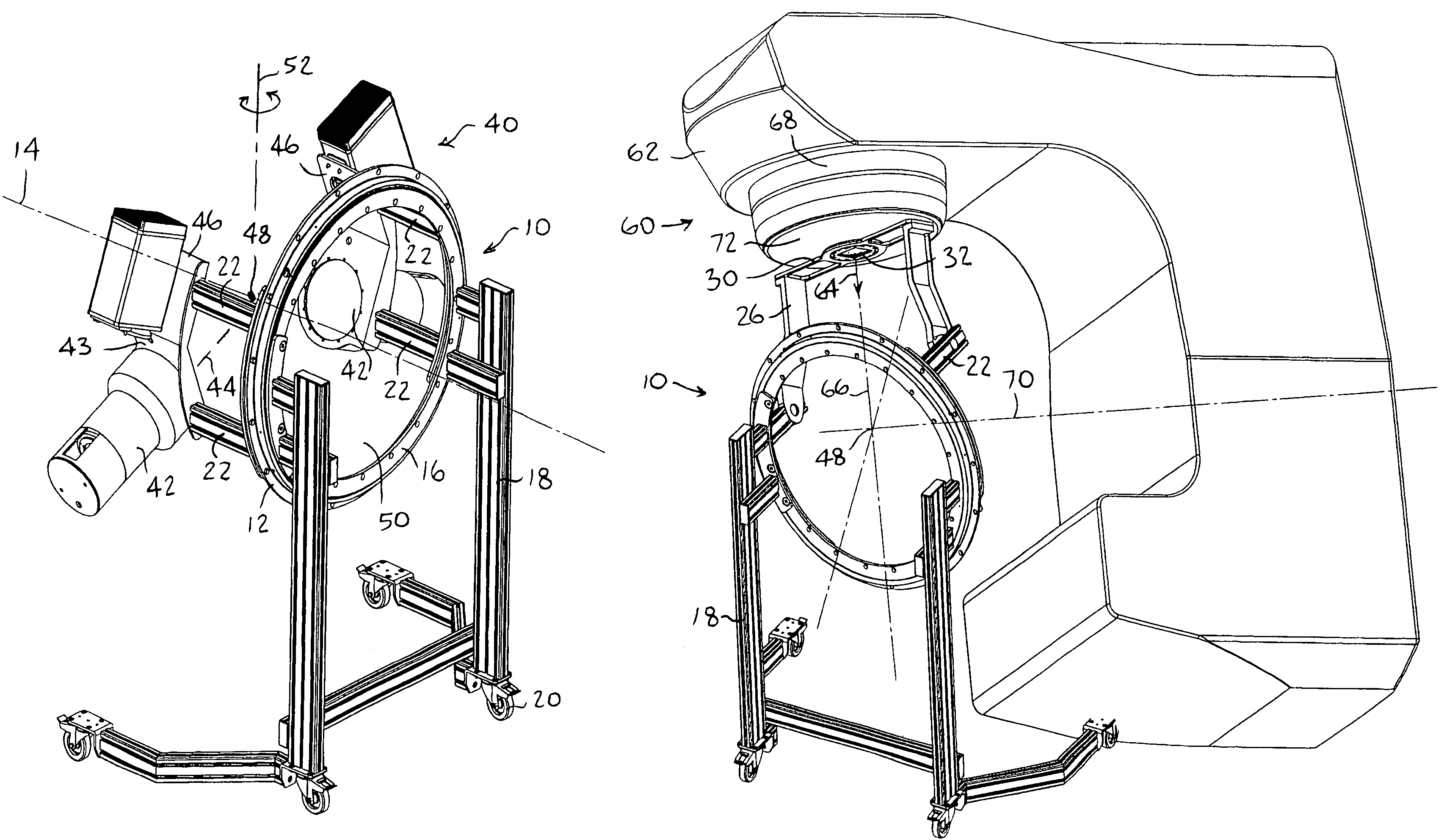
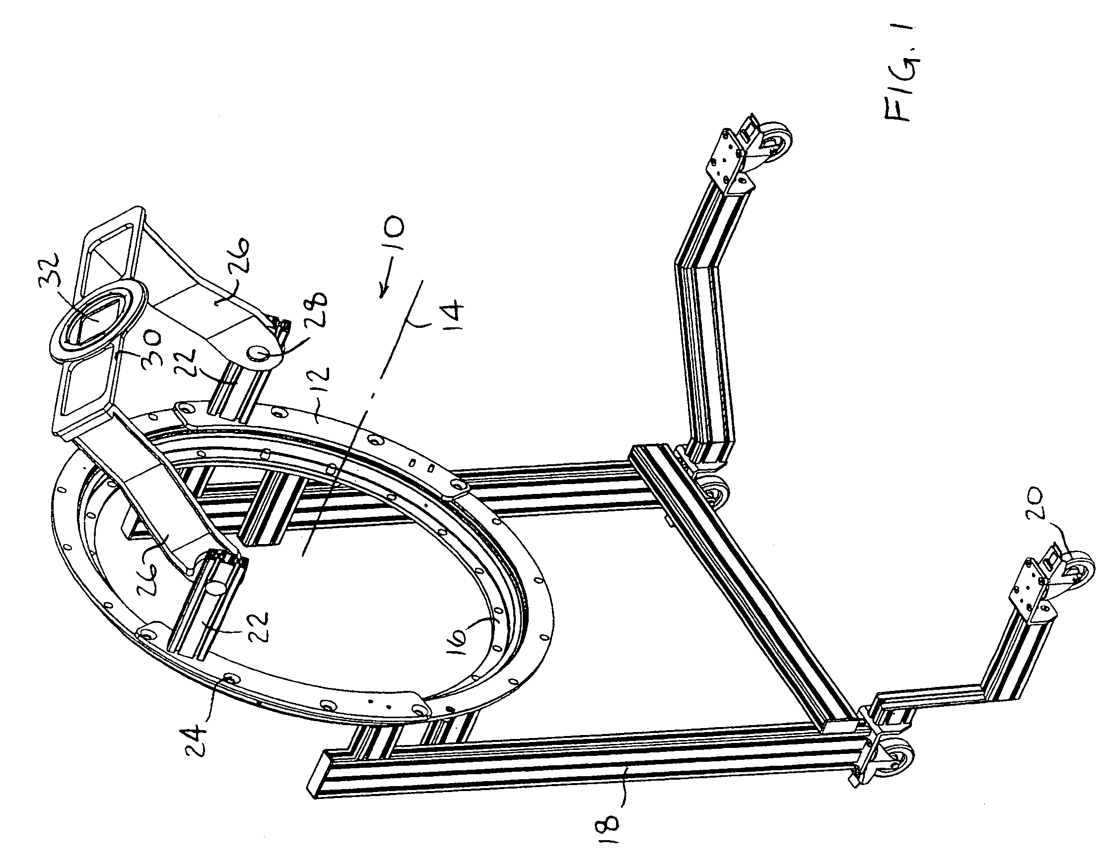
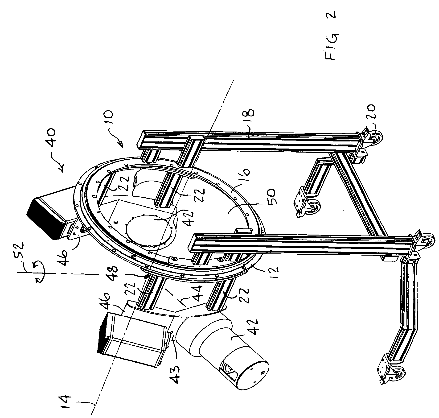
[0020]Reference is made to FIG. 1, which illustrates a coupler 10 for an imaging system, constructed and operative in accordance with an embodiment of the present invention.

[0021]The coupler 10 may include a rotator 12 having a hollow bore 50 for a patient to move therein and thereout. Although rotator 12 is shown as a ring, it does not necessarily have to be a ring, but rather any structure with hollow bore 50. Rotator 12 is rotatable about a longitudinal axis 14. For example, rotator 12 may be rotatingly mounted (e.g., by ball bearing races) to a stationary ring 16 that is fixed to a frame 18. Frame 18 may be portable, such as by being mounted on wheels or castors 20. One or more linkage arms 22 may extend from rotator 12. As seen in FIG. 1, linkage arms 22 may be attached to different mounting provisions 24 (e.g., mounting holes on rotator 12) spaced about axis 14. For example, linkage arms 22 may be mounted 180° part on rotator 12, or at any other angular separation. One or more...


PUM


Abstract

An imaging device including a rotator having a hollow bore for a patient to move therein and thereout, the rotator being rotatable about a longitudinal axis, at least one linkage arm extending outwards from the rotator, and imaging apparatus mounted on the at least one linkage arm, the imaging apparatus including an imaging source that emits an imaging beam to an imaging detector aligned therewith along an imaging direction, the at least one linkage arm capable of full axial rotation about an imaging isocenter along an entire length of the patient, the isocenter lying along a longitudinal axis, and wherein the imaging apparatus is operative to rotate and to capture images of the patient along the imaging direction as the patient is positioned at an angle in a range of about 0-90° inclusive with respect to the longitudinal axis.

Description

FIELD OF THE INVENTION[0001]The present invention relates generally to imaging and treatment systems, such as but not limited to, an x-ray or fluoroscope imaging system combined with a linear accelerator, wherein a spatial relationship is maintained between the imaging system and the treatment system such that beams from both systems intersect at a common isocenter.BACKGROUND OF THE INVENTION[0002]A CT (computerized tomography) scanner has a large hollow bore into which a patient is inserted longitudinally for imaging. The patient moves generally longitudinally with respect to the scanner (which is typically stationary), and the scanning may be done for a full revolution about the longitudinal axis. No rotation is available for other axes. If need be, the patient can be moved afterwards to a treatment area.[0003]A typical prior art C-arm is a device with an imaging source (e.g., x-ray generator) mounted on one end of the C-arm and an image detector on the other end of the C-arm. The...

Claims


Application Information

Patent Timeline
Patent Type & Authority Patents(United States)
IPC IPC(8): A61B6/08A61N5/10
CPCA61B6/4441A61N5/1049A61N5/1081A61N2005/1063A61N2005/1061
Inventor EIN-GAL, MOSHE
Owner EIN GAL MOSHE
Why Eureka
Try Eureka