Low power, low noise figure, latch driver circuit

a driver circuit and low power technology, applied in the field of radio frequency receivers, can solve the problems of linear amplifiers themselves consuming excessive power, p /sub,

Inactive Publication Date: 2007-11-20
AIR FORCE GOVERNMENT OF THE US SEC
View PDF4 Cites 6 Cited by
  • Summary
  • Abstract
  • Description
  • Claims
  • Application Information

AI Technical Summary

Benefits of technology

[0010]In an aspect, the driver circuit may further include a signal conditioning stage coupled to the differential amplifier stage. The signal conditioning stage is adapted to provide preliminary filtering to the first and second amplified signals for removing predetermined harmonic signal content from the first and second amplified signals while minimizing any signal amplitude degradation to the first and second amplified signals. In one aspect, the signal conditioning stage may include a first inductor and capacitor pair coupled in parallel and having first and second terminals. The first terminal of the first inductor and capacitor pair may be coupled to the supply and the second terminal of the first inductor and capacitor pair may be coupled to a first terminal of a first resistor. A second terminal of the first resistor may be coupled to communicate with the first amplified signal.

Problems solved by technology

One drawback or disadvantage to using a linear amplifier to boost the power level of the LO signal from 0 dBm to 10 dBm and to provide the minimum peak-to-peak current of 40 mAp-p is the excessive power required by the linear amplifier itself.

Method used


Image

  • Low power, low noise figure, latch driver circuit
  • Low power, low noise figure, latch driver circuit
  • Low power, low noise figure, latch driver circuit

Examples


Embodiment Construction

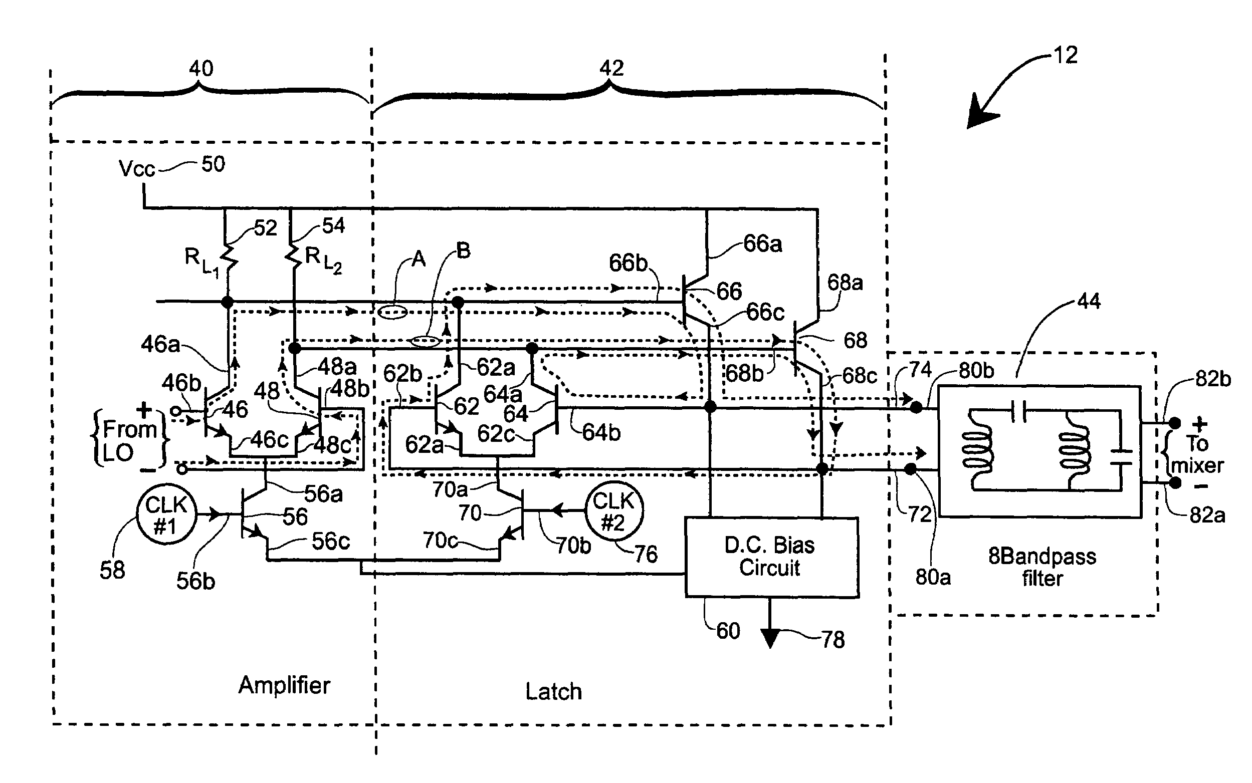
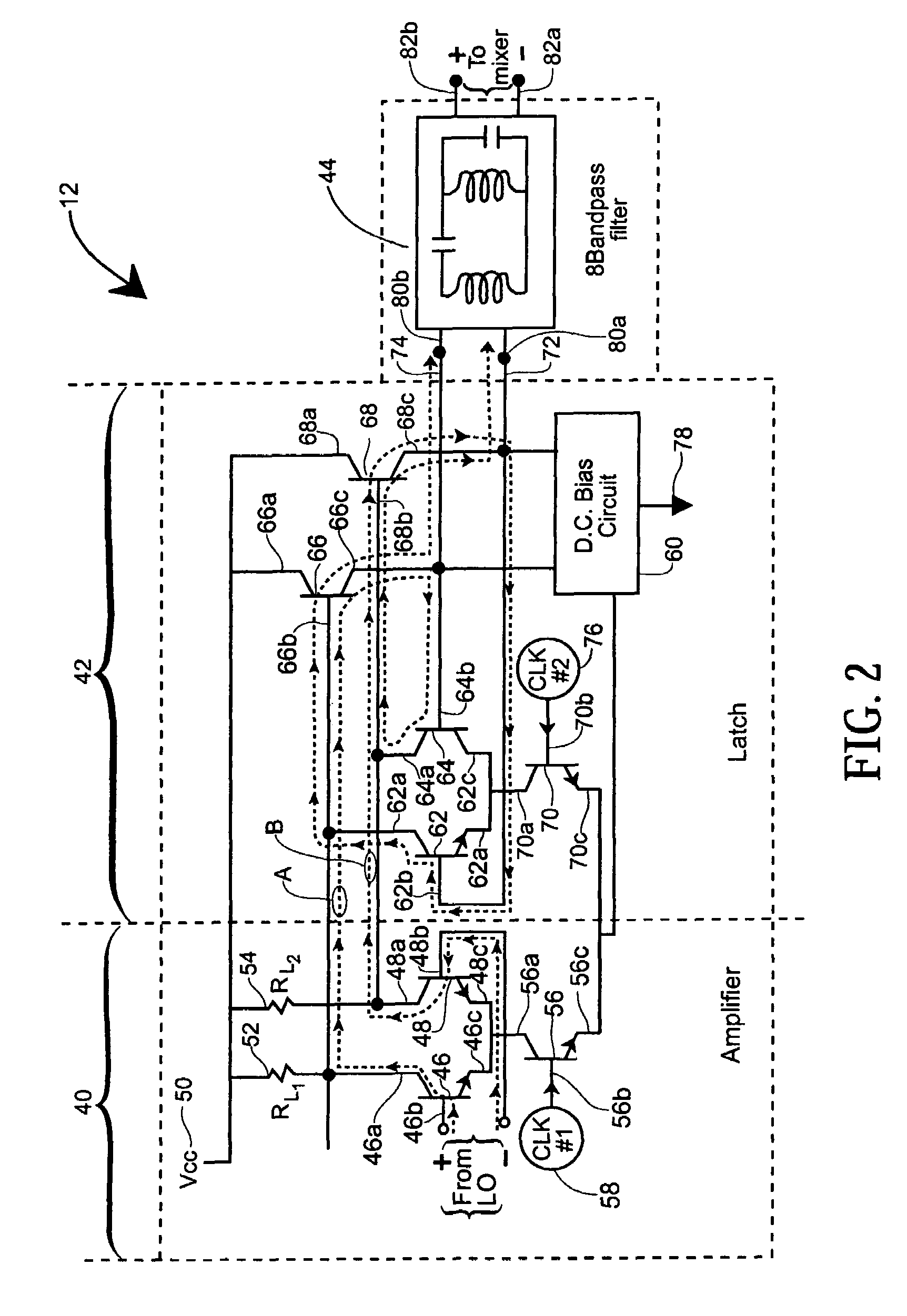
[0021]The present invention provides a relatively low power, low noise figure, latch driver circuit. The latch driver circuit may be employed to drive a number of devices and / or circuits, such as a passive mixer of an RF receiver, which may be incorporated in a radar system, wire-less telecommunication device and the like. When the latch driver circuit is incorporated in a radar system, such as a phased array radar systems which itself may incorporate a number of RF receivers, the overall power consumption and noise figure of the radar system may be significantly reduced, as will be described in further detail below.

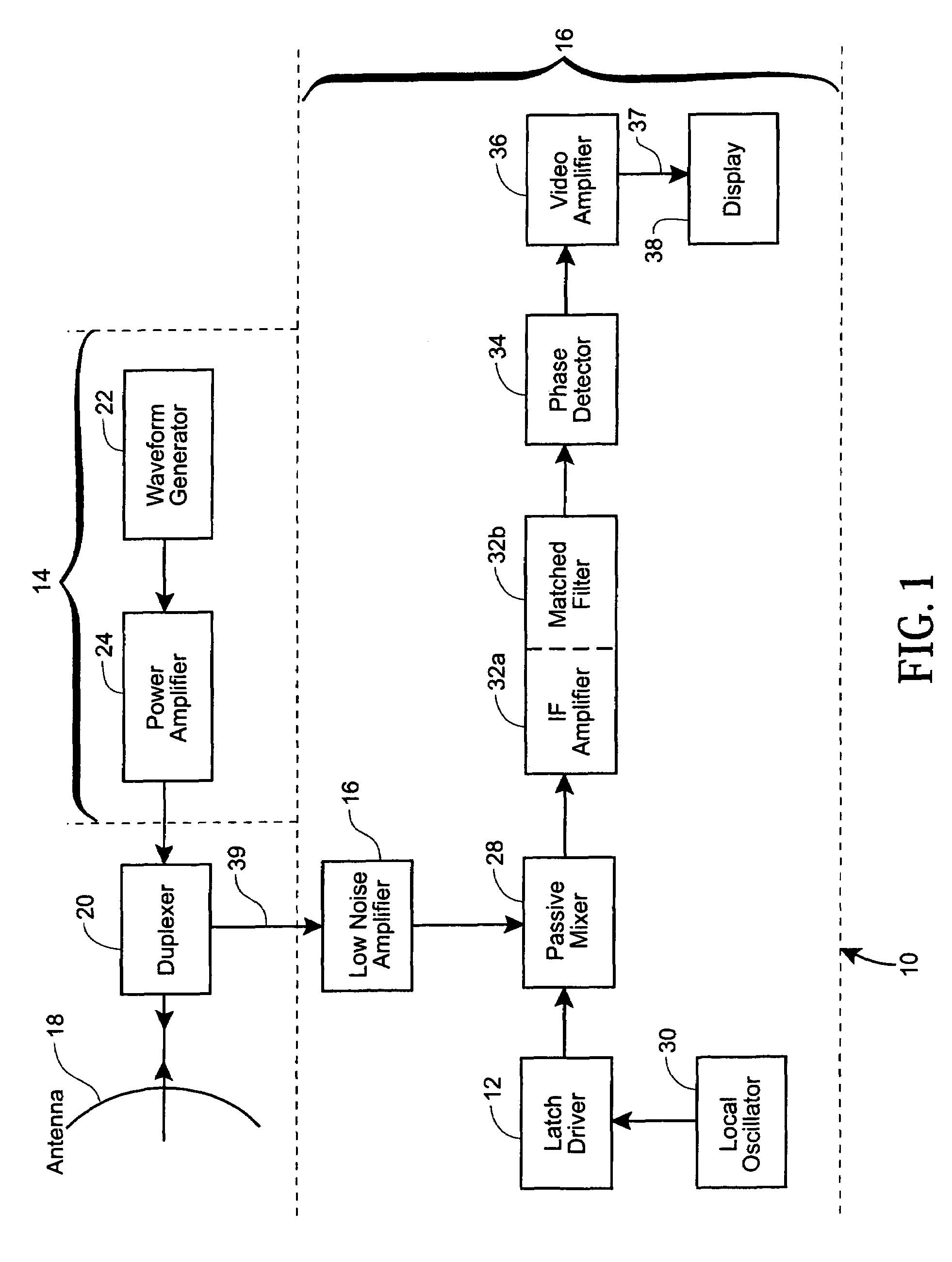
[0022]Referring now to FIG. 1, in an exemplary embodiment, shown is a high level functional block diagram of a radar system 10 incorporating the latch driver circuit 12 of the present invention. The radar system 10 includes an RF transmitter portion 14 and an RF receiver portion 16. The RF transmitter and receiver portions 14, 16 of the radar system 10 are both coupled t...


PUM


Abstract

A latch driver circuit is provided as a local oscillator driver for driving a passive mixer of an RF receiver. The driver circuit includes a differential amplifier stage coupled to a supply and a biasing circuit. The amplifier stage is operative to receive and process first and second input signals from a local oscillator for providing first and second amplified signals. The driver circuit further includes a latch stage coupled to the differential amplifier stage, which is operative to receive and process the first and second amplified signals for providing latched versions thereof. A filtering stage of the latch driver circuit is operative to receive and filter the latched versions of the first and second amplified signals for providing first and second mixer signals. Each of the first and second mixer signals includes signal content associated with a fundamental frequency particularly tuned for driving the passive mixer circuit.

Description

CROSS REFERENCE TO RELATED APPLICATIONS[0001]Not Applicable.STATEMENT REGARDING FEDERALLY SPONSORED RESEARCH[0002]Not Applicable.FIELD OF THE INVENTION[0003]The present invention relates generally to radio frequency (RF) receivers and, more particularly, to a latch driver circuit employed as a local oscillator driver for driving a passive mixer of an RF receiver.BACKGROUND OF THE INVENTION[0004]As is known, a passive mixer is often used in a linear RF receiver system to meet stringent linearity and noise requirements. An example of a passive mixer is a double balanced resistive Field Effect Transistor (FET) mixer, where all the ports are operated differentially. In the FET mixer, local oscillator (LO) signals are applied to the gates, RF signals are applied to sources (or drains) and intermediate frequency (IF) signals are taken from the drains (or sources). In order to achieve the high linearity and low noise requirements, a relatively large LO signal is required, which LO signal i...

Claims


Application Information

Patent Timeline
Patent Type & Authority Patents(United States)
IPC IPC(8): H04B1/16
CPCH04B1/26H03D7/125H03B2200/0034
Inventor KIM, HELEN
Owner AIR FORCE GOVERNMENT OF THE US SEC
Why Eureka
Try Eureka