Device and method for attenuating an anti-resonant circuit

A technology of oscillation circuit and attenuation circuit, which is applied in the field of attenuation parallel oscillation circuit devices, can solve problems such as inability to get out, and achieve the effect of reducing signal amplitude

Inactive Publication Date: 2007-11-14
ROBERT BOSCH GMBH
View PDF0 Cites 4 Cited by
  • Summary
  • Abstract
  • Description
  • Claims
  • Application Information

AI Technical Summary

Problems solved by technology

For signal amplitudes in the range between 0.25 V and 3.1 V, however, no attenuation linearly related to the signal amplitude in the parallel oscillator circuit results, because on the one hand the clamping diodes are not yet conducting, while on the other hand the op amp is in saturation

Method used


Image

  • Device and method for attenuating an anti-resonant circuit
  • Device and method for attenuating an anti-resonant circuit
  • Device and method for attenuating an anti-resonant circuit

Examples


Embodiment Construction

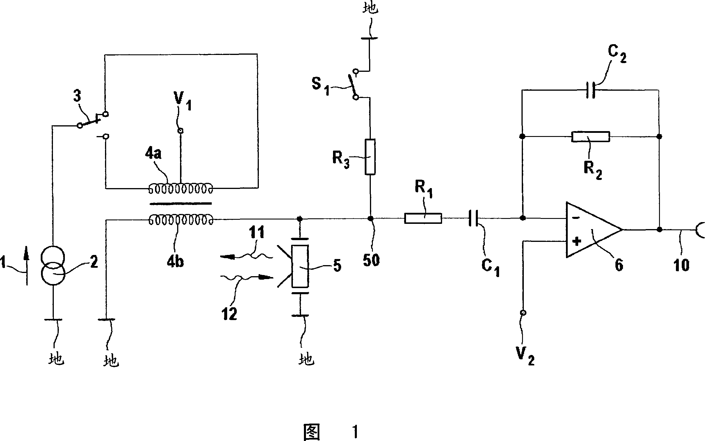
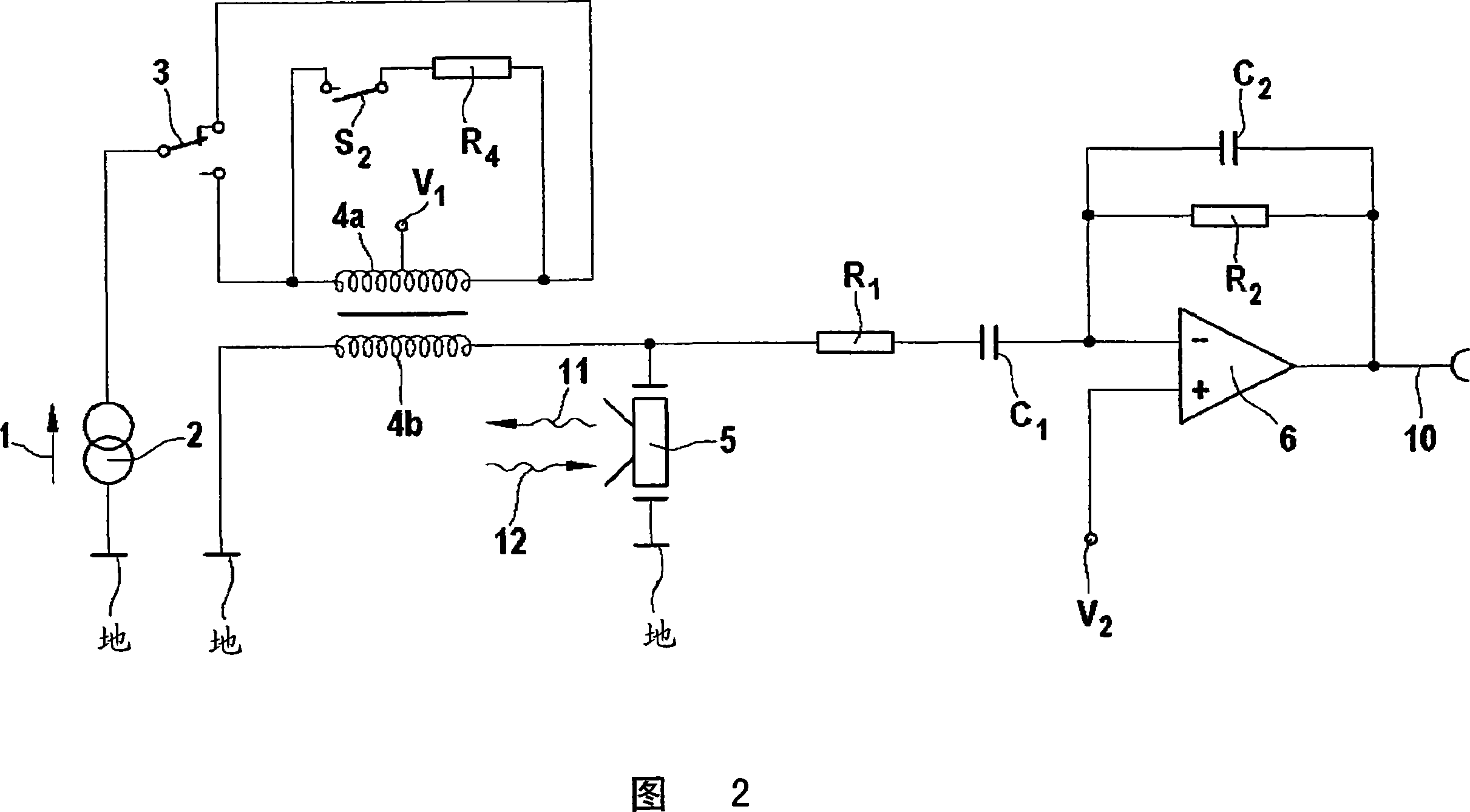
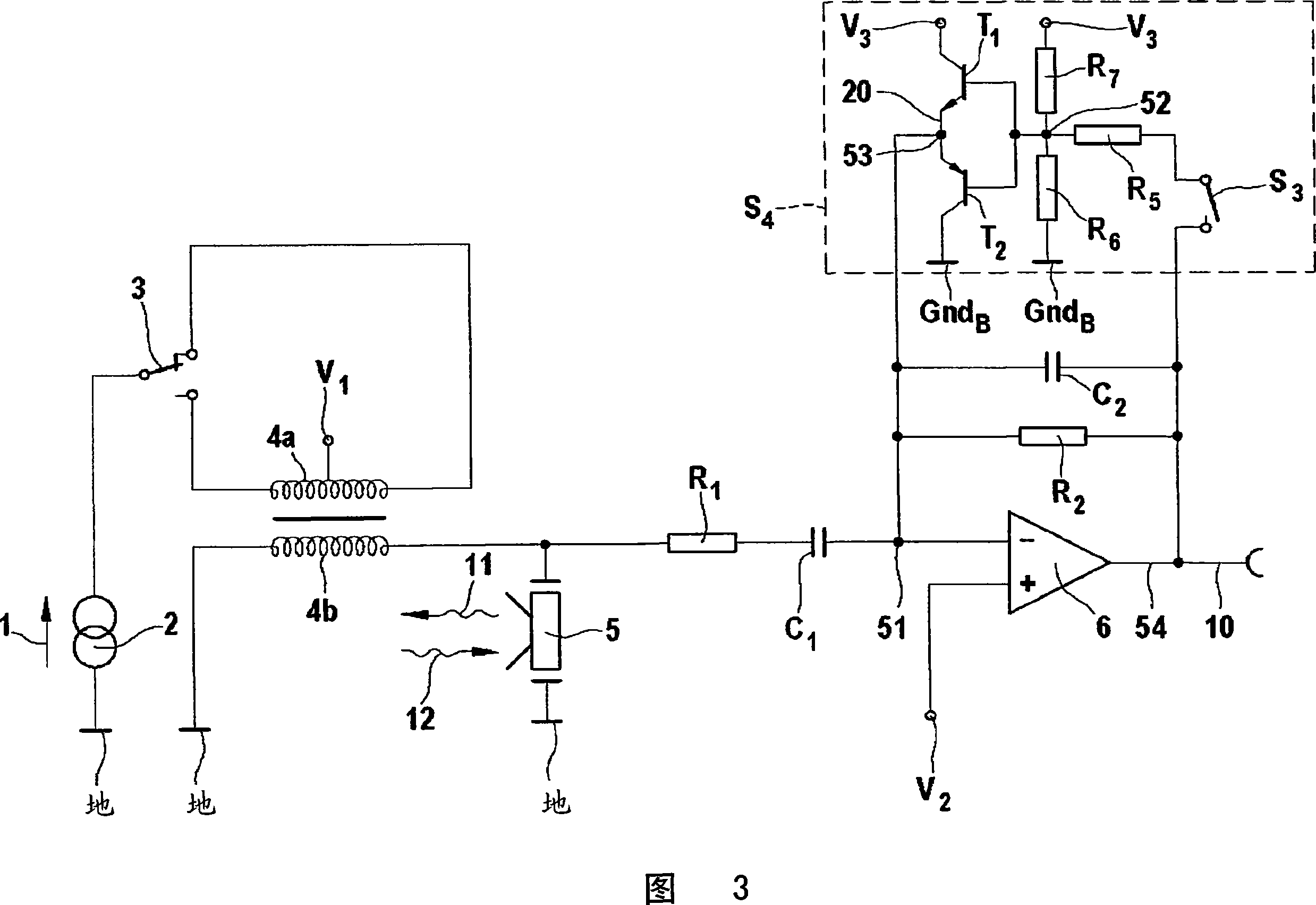
[0029] In the figures, the same reference numerals refer to the same components or components with the same function, so that they are not described one by one.

[0030] A schematic diagram of a first embodiment of the invention is shown in FIG. 1 . An acoustic transducer 5 plays the role of transmitting ultrasonic signals 11 and receiving reflected ultrasonic signals 12 . The ultrasonic signal 11 is advantageously transmitted in pulses. By measuring the period of time that an emitted ultrasonic signal 11 takes before it is received as a reflected ultrasonic signal 12 , the distance to an object at which the ultrasonic signal 11 is reflected can be determined. This can mainly be used for parking assistance of the car. Due to the sound propagation speed of 330 / s, a distance of about 15 cm to the sound transducer results in a propagation time of about one millisecond.

[0031]The sound transducer 5 can be formed by a cavity membrane which is moved by a piezoelectric actuator....


PUM


Abstract

A backlight unit includes a plurality of fluorescent lamps driven by one inverter in a manner to prevent wave noise. A first common electrode line connects respective first ends of the odd numbered fluorescent lamps in common. A second common electrode line connects respective first ends of the even numbered fluorescent lamps in common. A third common electrode line connects the second ends of the odd and even numbered fluorescent lamps in common. Voltages having opposite phases are respectively applied to the first common electrode line and the second common electrode line.

Description

technical field [0001] The present invention relates to an apparatus and method for attenuating a parallel oscillating circuit. Background technique [0002] Although the invention has been described with reference to an ultrasonic transducer for a parking aid, the invention is not limited thereto. [0003] In order to determine the distance of one car from another, the travel time of an ultrasonic pulse over the distance it travels to and back from the car in front can be measured. For this purpose, an ultrasonic transducer generates an ultrasonic signal in the form of pulses. An ultrasonic sensor detects the reflected portion of the ultrasonic signal and a downstream device determines the propagation time. A propagation time of 0.5 ms results from a sound propagation velocity of approximately 330 / s with a distance of approximately 7.5 cm to the vehicle ahead. [0004] The ultrasound signal is typically generated by an acoustic transducer in which a piezoelectric actuato...

Claims


Application Information

Patent Timeline
Patent Type & Authority Applications(China)
IPC IPC(8): H04R3/00G01S15/10
CPCB06B1/0215H03J5/246H03J3/20B06B2201/30G01S7/524Y10S367/903
Inventor M·雷彻
Owner ROBERT BOSCH GMBH
Why Eureka
Try Eureka