High bandwidth memory interface

a memory interface and high-bandwidth technology, applied in the direction of instruments, generating/distributing signals, sustainable buildings, etc., can solve the problems of time-consuming and labor-intensive, time-consuming and labor-intensive, and the need for more complicated interaction between memories and microprocessors/microcontrollers, so as to improve the high-bandwidth chip-to-chip interface, maintain error-free data transmission, and improve the speed

Inactive Publication Date: 2007-11-20
CONVERSANT INTPROP MANAGEMENT INC
View PDF13 Cites 72 Cited by
  • Summary
  • Abstract
  • Description
  • Claims
  • Application Information

AI Technical Summary

Benefits of technology

[0024]Accordingly, one object of the present invention is to provide an improved high bandwidth chip-to-chip interface for memory devices, which is capable of operating at higher speeds, while maintaining error free data transmission, consuming lower power, and supporting more load.
[0025]Another object of the invention is to eliminate the requirement for a separate clock generator chip.
[0029]A still yet even further object is to provide a means to expand the number of memory devices that can be supported by a single controller.
[0041]A further aspect of the invention provides a memory subsystem loopback clock architecture including a push pull I / O. This allows both rising and falling edges to be used for sampling data, thereby reducing the sensitivity of the system to clock duty cycle variation. This approach also saves power in the device itself allowing more cost-effective packaging.
[0043]A further aspect of the invention provides a memory subsystem wherein a repeater appears as a single load on the main bus but drives a set of signals identically to the controller to create a sub-bus on which memory devices can be connected. The repeater acts as a controller on this sub-bus and memory devices cannot distinguish between the main bus and the sub-bus and therefore, operate identically on either one. The increased latency of devices on the sub-bus compared to those connected directly to the main bus may be corrected by the controller by scheduling activity appropriately.
[0044]A still further aspect of the invention provides a memory subsystem, wherein the semiconductor devices include series stub resistors wherein the main bus is routed through the device to mitigate the effects of the stubs. Furthermore conventional TSOP type packaging is used for lower cost.

Problems solved by technology

This large storage capability comes with the price of slower access time and the requirement for more complicated interaction between memories and microprocessors / microcontrollers than in the case of say static random access memories (SRAMs) or non-volatile memories.
These timing errors may occur due to any one or a combination of static phase offset, timing jitter and wander resulting from inaccuracies and mismatches within the components making up the DLL / PLL loop.
Since the DLL / PLL outputs a 50 / 50 duty cycle signal, while the data inputs may have a degraded duty cycle due to the aforementioned asymmetrical drive problem, this results in a further error in positioning the clock for optimal data sampling.
The timing errors between clock and data created at the transmitting device and the receiving device are cumulative and can result in data errors.
Similarly to the input data case, timing errors between clock and data are cumulative and can result in data errors.
Because the falling edge of the clock is created by a clock generator pulldown transistor (not shown), while the rising edge is created by the bus termination resistor, it is difficult to match pulse rise time and pulse fall time.
This can lead to non-symmetric duty cycle on the clock bus.
However, this approach creates an internal sampling instant that is unrelated to the data edge of the bit being sampled, compounding the effects described above and resulting in further closure of the data eye, since subsequent data bits cannot be known in advance whereas a clock sequence is repetitive and therefore, determinable in advance.
Inaccuracies in any of these elements may lead the output amplitudes from different devices to vary, resulting in further closure of the data eye.
The number of devices in a the prior art configuration described above is limited to 32 because of the loading and length of the bus.
If a larger memory configuration is required the controller must support several busses in parallel, consuming additional pins, silicon area, and power.
This stub can cause reflections on the bus to the detriment of signal integrity.
Ultimately, the maximum frequency at which the system can operate will be limited by the doubly loaded clock line.
As a result, write data sampling will not occur at the correct time.

Method used


Image

  • High bandwidth memory interface
  • High bandwidth memory interface
  • High bandwidth memory interface

Examples


Embodiment Construction

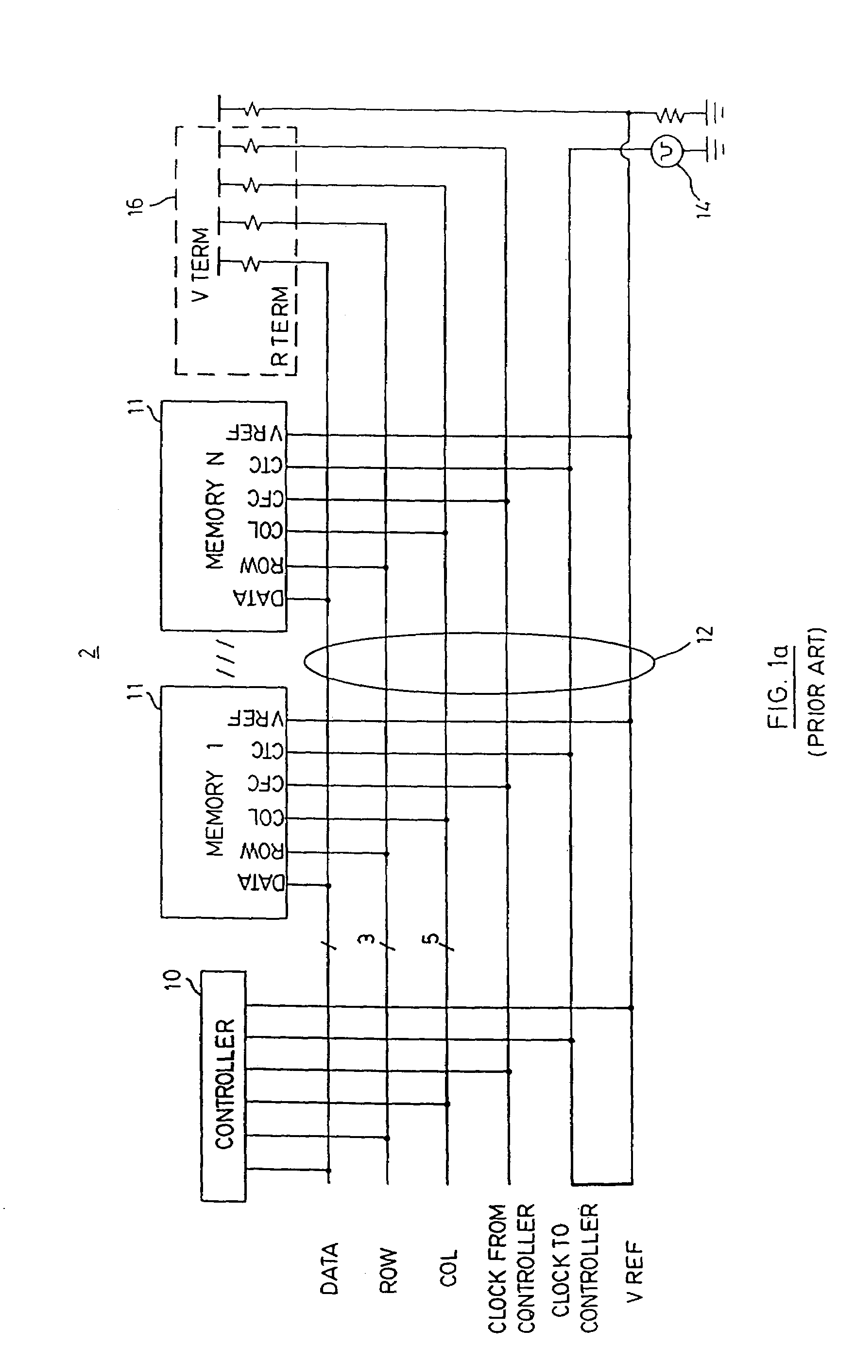
[0069]Referring to FIG. 1(a) a general prior art architecture on which the present memory subsystem is based is indicated by numeral 2 and is described in greater detail in R. Crisp “Direct Rambus Technology: The New Main Memory Standard”, IEEE Micro, November / December 1997, p. 18-28, incorporated herein by reference. The memory subsystem 2 includes a main bus or channel 12 which consists of a plurality of high speed controlled impedance matched transmission lines, a controller 10 and at least one memory device 11 connected thereto in parallel. The channel 12 has a bus topology with the controller 10 at one end, terminators 16 at the other end and memory devices II in-between. The transmission lines include a ClockToController line; a ClockFromController line; a data bus; a row bus and column bus each carrying correspondingly named signals. These signals are terminated at their characteristic impedance Rterm at the far end of the channel.

[0070]The terminators pull the signals up to ...


PUM


Abstract

This invention describes an improved high bandwidth chip-to-chip interface for memory devices, which is capable of operating at higher speeds, while maintaining error free data transmission, consuming lower power, and supporting more load. Accordingly, the invention provides a memory subsystem comprising at least two semiconductor devices; a main bus containing a plurality of bus lines for carrying substantially all data and command information needed by the devices, the semiconductor devices including at least one memory device connected in parallel to the bus; the bus lines including respective row command lines and column command lines; a clock generator for coupling to a clock line, the devices including clock inputs for coupling to the clock line; and the devices including programmable delay elements coupled to the clock inputs to delay the clock edges for setting an input data sampling time of the memory device.

Description

[0001]This application is a Continuation Application from U.S. application Ser. No. 10 / 247,821, filed Sep. 20, 2002, now U.S. Pat. No. 6,779,097, issued Aug. 17, 2004, which is a Continuation Application from U.S. application Ser. No. 09 / 182,494, filed Oct. 30, 1998, now U.S. Pat. No. 6,510,503, issued Jan. 21, 2003, which claims priority from Canadian Application Serial No. 2,243,892, filed Jul. 27, 1998.[0002]The present invention relates to computer memory interfaces and more specifically to chip-to-chip interfaces for dynamic random access type memories capable of operating at high speed. This application incorporates herein by reference Canadian Patent Application Number 2,243,892 filed on Jul. 27, 1998.BACKGROUND TO THE INVENTION[0003]The evolution of the dynamic random access memories used in computer systems has been driven by ever-increasing speed requirements mainly dictated by the microprocessor industry. Dynamic random access memories (DRAMs) have generally been the pred...

Claims


Application Information

Patent Timeline
Patent Type & Authority Patents(United States)
IPC IPC(8): G06F13/00G06F13/42
CPCG06F13/1689G06F13/4234G06F13/4243G11C8/18G06F1/12G11C5/06Y02B60/1235Y02B60/1228Y02D10/00
Inventor GILLINGHAM, PETERMILLAR, BRUCE
Owner CONVERSANT INTPROP MANAGEMENT INC
Why Eureka
Try Eureka