Solar thermal roofing

a solar thermal and roofing technology, applied in solar heat collectors with working fluids, solar heat collectors for particular environments, photovoltaics, etc., can solve the problems of lack of insulative covering, energy capture, time and cost in interconnection,

Inactive Publication Date: 2007-11-27
BROATCH PETER MARTIN
View PDF17 Cites 27 Cited by
  • Summary
  • Abstract
  • Description
  • Claims
  • Application Information

AI Technical Summary

Benefits of technology

[0013]It is an object of the present invention to provide solar thermal roofing (or walling, since the invention is equally applicable to v

Problems solved by technology

The amount of energy captured depends upon the size of the collector, which is naturally limited by handling and aesthetic considerations, particularly when the collector is roof-mounted.
For a thermal system, however, conventional flat plate collectors, if reduced to the size of a typical roof tile, would entail unacceptable time and cost in interconnection.
This system lacks any insulative covering for the tiles, which would thereby suffer considerable heat loss from convection, and even more so when subject to precipitation and afterwards due to evaporation.
However it is proposed that co

Method used


Image

  • Solar thermal roofing
  • Solar thermal roofing
  • Solar thermal roofing

Examples


Embodiment Construction

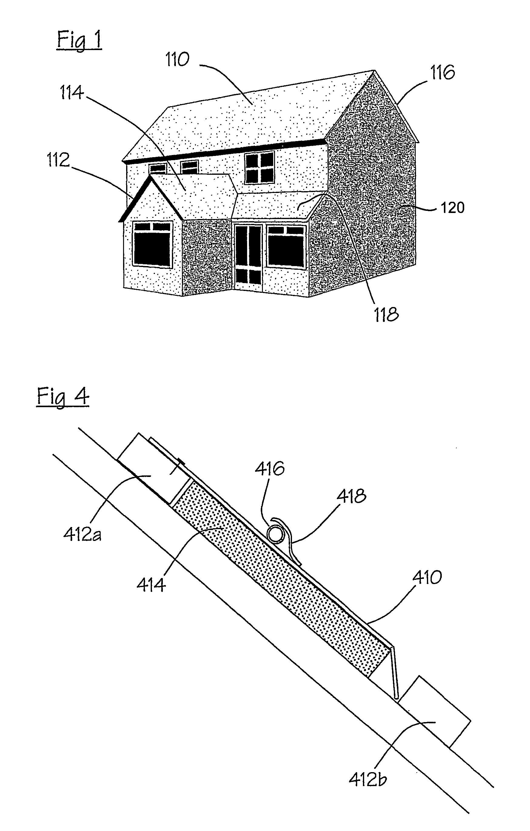
[0027]Referring first to FIG. 1, the house shown therein has a roof face 110. As will be described in more detail hereinafter, the roof face 110 is arranged as a solar thermal collector. The roof face 110 is chosen for this purpose because it is disposed generally towards the Equator (in contrast to the roof faces 112, 114 and 116) and because it is large (in comparison with the porch roof face 118).

[0028]It may be noted that if the disposition of the house of FIG. 1 were (as viewed from above) turned through 90° clockwise, the roof face 114 would then face the Equator and could be used as a solar collector instead of the face 110. However, in this disposition it would be better to use the wall face 120 because of its greater size. (The invention is applicable to wall faces as well as to roof faces).

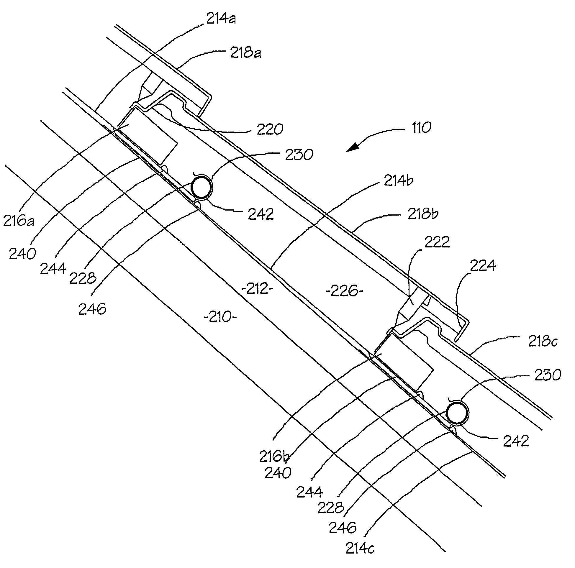
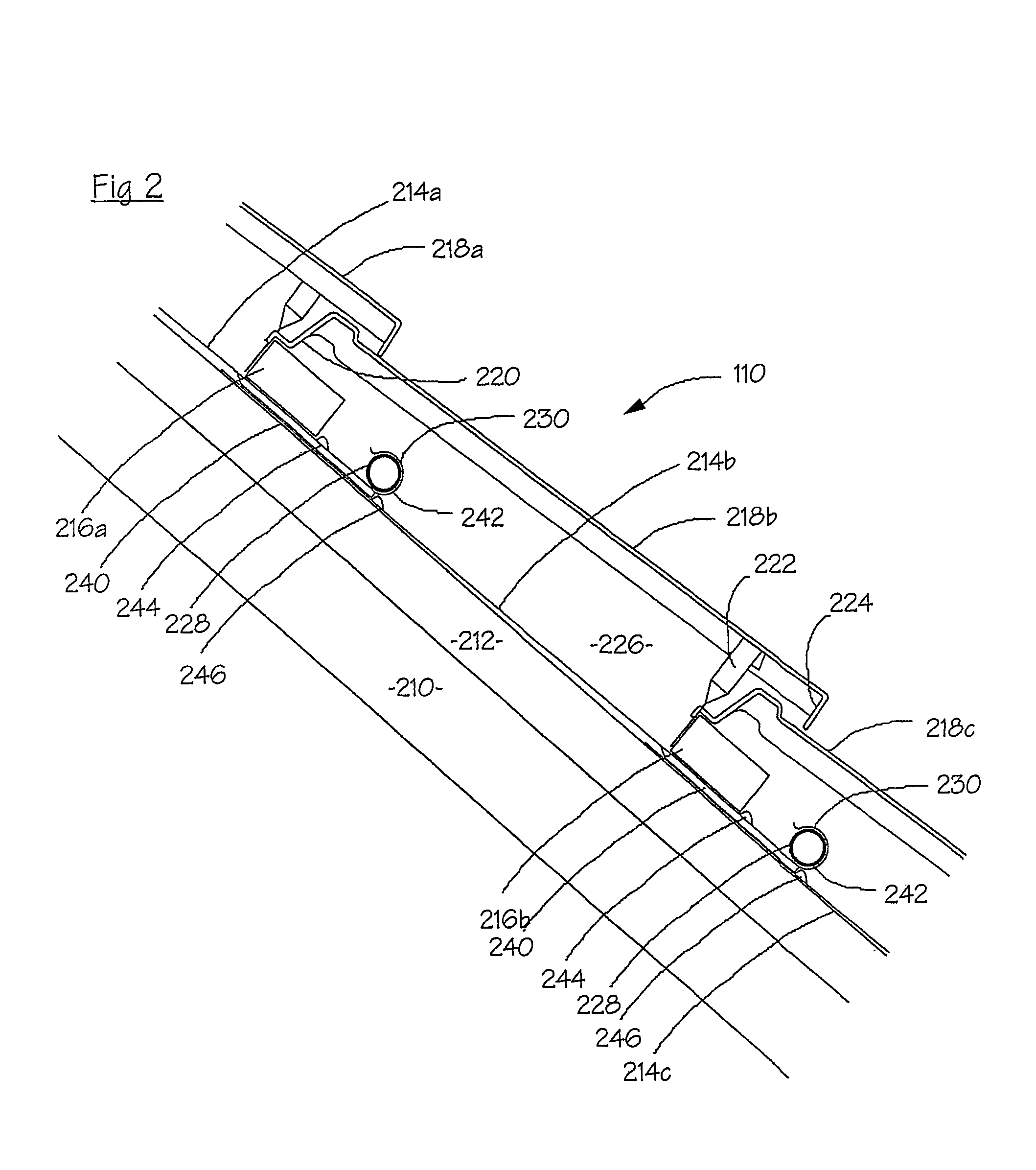
[0029]Referring now to FIG. 2, this shows that the roof face 110 comprises a thermally insulative layer 210 and a plurality of counter battens 212 secured over the layer 210. The counter...


PUM


Abstract

An external building surface formed by at least one of a roof and a wall, the external building surface comprising a plurality of battens spaced apart to define a plurality of transverse courses, a plurality of tiles supported by the battens in the courses defined thereby to provide an outer layer of said external building surface, which tiles are transparent to solar radiation, a plurality of strips arranged one for each course to form an inner layer substantially coextensive with the outer layer, which strips are absorbent to solar radiation, and a duct for a fluid heat transfer medium of a solar heating system extending lengthwise of the strips so that in use the fluid medium is heated when the strips absorb solar radiation incident through the tiles, wherein in each course there is a space wherein air is held over and along the strip in that course.

Description

[0001]This application is the US national phase of international application PCT / GB01 / 04440 filed 5 Oct. 2001, which designated the US.FIELD OF THE INVENTION [0002]This invention concerns solar thermal roofing, which is to say roofing which collects heat from sunlight for space or water heating.BACKGROUND OF THE INVENTION [0003]It is well known that solar energy may be used to provide hot water, and this is common in tropical and sub-tropical countries. In higher latitudes the gain is less but still beneficial. In Britain, for instance, solar energy can provide domestic hot water for an average family through the summer months and a useful top-up (by pre-heating the water supply) through the rest of the year. Over the course of a year a south-facing roof in Britain receives about 1000 kWh / m2, which is clearly an important potential source of energy.[0004]Typically the solar energy is captured by means of a so-called flat plate collector which is often mounted upon a roof. The collec...

Claims


Application Information

Patent Timeline
IPC IPC(8): E04D13/18F24J2/04F24S10/70
CPCF24J2/0455Y02E10/44Y02B10/20F24S20/69Y02E10/40
Inventor BROATCH, PETER MARTIN
Owner BROATCH PETER MARTIN
Why Eureka
Try Eureka