Surgical instrument

a surgical instrument and working element technology, applied in the field of surgical instruments, can solve the problems of poor mechanical feedback of damage to tissue, and inability to correctly feed the force exerted on the working element to the operating mechanism of the instrument, so as to achieve the effect of keeping in use reliably and inexpensively, and difficult sterilization

Inactive Publication Date: 2007-11-27
VLEUGELS HLDG
View PDF7 Cites 1641 Cited by
  • Summary
  • Abstract
  • Description
  • Claims
  • Application Information

AI Technical Summary

Benefits of technology

[0012]The sensors, actuators and the control unit are preferably integrated in the instrument or secured directly to the instrument. As a result, the instrument remains easy to handle, so that the user finds it easy to use and can be very flexible in his movements. The instrument according to the invention can be designed advantageously with dimensions substantially corresponding to the dimensions of conventional minimally invasive instruments or an only slightly enlarged version thereof.
[0014]The impedance of a specific material is a good measure of the feeling provided by a material of this type when it is touched. The control unit according to the invention advantageously feeds the impedance to which the working element of the instrument is subject back to the operating element, so that the user has a very realistic “feeling” of the tissue or the like which is being manipulated by the working element.
[0020]The control unit preferably determines an impedance to which the operating element is subject on the basis of the force which is exerted on the operating element, the position and speed of the operating element, which impedance is likewise fed back to the actuators. In this way, the feedback of feeling is improved still further. In this case, the force on the operating element and the position of the operating element are measured by means of a second force sensor and position sensor, respectively. The speed is preferably determined as a derivative over the course of time of the position signal measured by the second position sensor.
[0022]Sensors of this type have the advantage over more conventional sensors in that no electrical signals are used at least in the vicinity of the working element. The use of electrical signals is undesirable, since the measurement signals from the sensors may be interfered with by other equipment present in the operating theater. Moreover, glass fibres are inexpensive and take up little space.
[0027]The use of glass fibres makes the instrument as a whole more difficult to sterilize, since the glass fibres are damaged by heating. However, making the instrument disposable makes use of the instrument very expensive, on account of the electronics required for the control unit and the light sensor(s) and the actuators. By separating the expensive components, in particular electronics and actuators, of the instrument from the section of the instrument in which the glass fibres run, it is possible for the instrument to be kept in use reliably and inexpensively.

Problems solved by technology

The specific shape of the instruments, i.e relatively narrow and elongate, which are used result in more friction in relative terms, and the instruments are more flexible, with the result that the mechanical feedback of the force exerted on the working element to the operating mechanism is less good.
Consequently, it is possible, for example, that he may damage tissue as a result of clamping it too hard.
However, on account of the specific shape required for instruments for minimally invasive surgery, friction and hysteresis are still present in the design, and consequently the force which is exerted on the working element of the instrument is not correctly fed back to the operating mechanism of the instrument.
As a result, the user of an instrument of this type does not have an optimum “feeling” for the tissue or the like which he is manipulating with the instrument.
It is then difficult for a surgeon to position the working element of the instrument accurately.

Method used


Image

  • Surgical instrument
  • Surgical instrument
  • Surgical instrument

Examples


Embodiment Construction

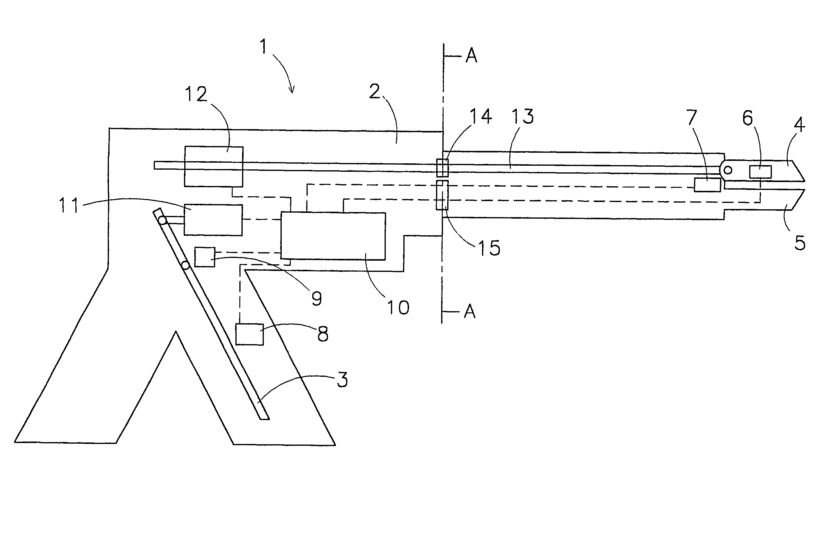
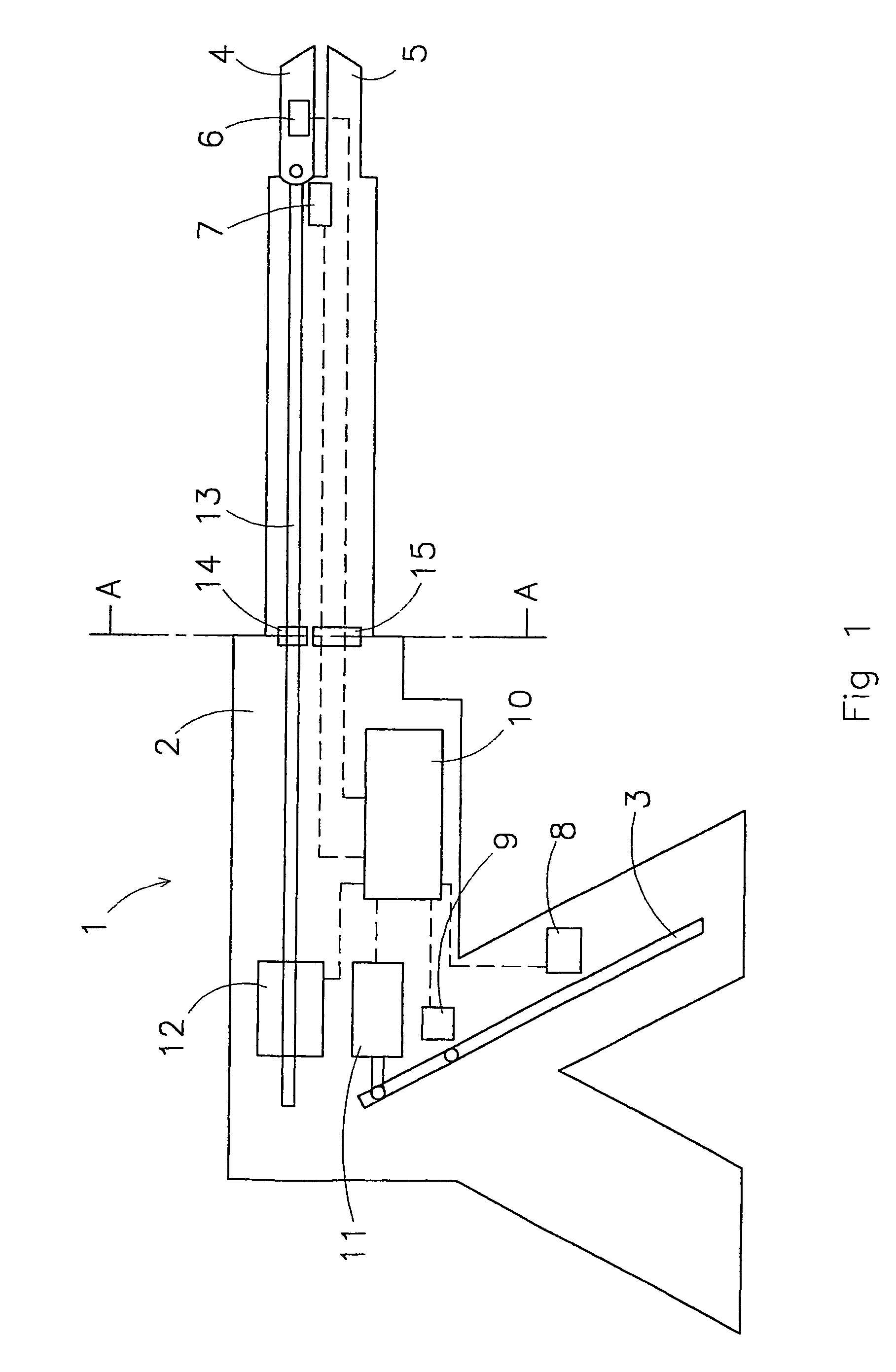
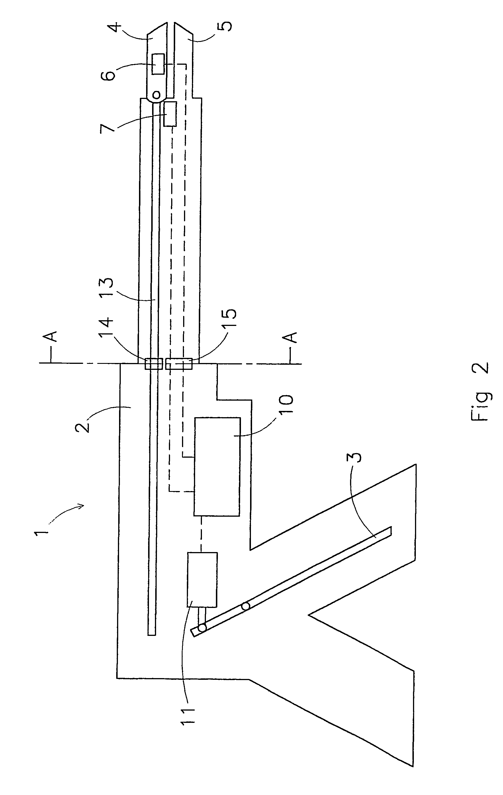
[0036]FIG. 1 shows a first preferred embodiment of the instrument according to the invention, denoted overall by reference numeral 1. The various components of the instrument 1 are diagrammatically depicted in the figure. The instrument 1 comprises an elongate frame 2 having, at a first end, at least one operating element 3 and, at the second end, a working element 4 which is moveably secured to the frame and a second working element 5 which in this case is fixed to the frame and forms a component thereof. It is also possible to make a second working element moveable with respect to the frame and to provide more than two fixed or moveable working elements.

[0037]A force sensor 6 for measuring the force which is exerted on the working element 4 and a position sensor 7 for measuring the position of the working element 4 with respect to the frame 2 are also arranged in or close to the working element 4. A force sensor 8 for measuring the force which is exerted on the operating element a...


PUM


Abstract

The invention relates to an instrument for surgery, in particular minimally invasive surgery. The instrument includes means for feeding back a force which is exerted on the working element of the instrument to the operating element. These means include at least a first force sensor for measuring the force which is exerted on the working element, a control unit and a first actuator. On the basis of a signal which originates from the first force sensor, the control unit controls at least the first actuator in order to control the operating element. Furthermore, the means preferably include a first position sensor for measuring a position of the working element with respect to the frame. The control unit advantageously determines an impedance which the working element is subject to as a result of the presence of a tissue or the like, on the basis of which impedance the control unit controls at least the first actuator.

Description

TECHNICAL FIELD OF THE INVENTION[0001]The present invention relates to an instrument for surgery, in particular minimally invasive surgery, which instrument comprises an elongate frame which, in the vicinity of a first end thereof, comprises an operating element, which can be operated manually, and, at a second end thereof, at least one working element which can move with respect to the frame.DESCRIPTION OF RELATED ART[0002]An instrument of this type is used in particular in surgical procedures which use minimally invasive operating techniques. In a minimally invasive operation of this type, a number of small incisions are made and instruments and the like can be inserted through these incisions. Generally, a cylindrical tube is placed into the incision and the instruments are placed through it. The instruments which are used in principle correspond to the instruments which are used in conventional operating techniques. However, a narrow and elongate instrument is required in order ...

Claims


Application Information

Patent Timeline
Patent Type & Authority Patents(United States)
IPC IPC(8): A61B17/00A61B17/28A61B19/00
CPCA61B17/29A61B19/22A61B2017/00022A61B2017/00026A61B2019/465A61B2017/0046A61B2019/223A61B2019/2292A61B2017/00398A61B34/70A61B34/35A61B34/76A61B2090/065
Inventor VLEUGELS, MICHEL PETRONELLA HUBERTUSLAZEROMS, MARKUS CORNELIS JAKOBUS
Owner VLEUGELS HLDG
Why Eureka
Try Eureka