Ground anchors with compression plates

a technology of compression plates and anchors, which is applied in the direction of anchors/canopies, waterborne vessels, vessel parts, etc., can solve the problems of short length, ineffective such as those sold under, and insufficient sand holding power of most anchors, so as to reduce the tendency of anchors, and limit the top of the anchor movement

Inactive Publication Date: 2007-12-04
BURNS PETER ROBERT
View PDF10 Cites 35 Cited by
  • Summary
  • Abstract
  • Description
  • Claims
  • Application Information

AI Technical Summary

Benefits of technology

[0029]In accordance with one or more aspects of one embodiment of the invention, a ground anchor has a single narrow tine with a compression plate attached orthogonally to the upper part of the tine. The tine is driven into the ground until the plate contacts the ground. When the top of the tine is under load, e.g., due to pull from a guy line or a tent canvas, the plate compresses the ground around the anchor, limiting movement of the top of the anchor. In response to this limited movement, the upper portion of the anchor flexes slightly due to the inherent springiness of the tine and the depth-limited movement of the lower part of the tine. When the load is removed, the anchor springably returns to its original condition. The lower portion remains secured in the ground, thus reducing the anchor's tendency to slip out or tear the ground into which it is inserted. The narrow tine, and its inherent flexibility, combine to ensure that great stiffness or rigidity, two attributes that cause a prior-art stake to fail, are reduced.

Problems solved by technology

Even though the angle is small, most anchors, such as those sold under the trademarks Danforth by Tie-Down Engineering of Atlanta, Ga., CQR by Lewmar of the U.K., and the like, do not have effective holding power in loose sand.
However, the projections used to engage the sea floor have a blunt shape and relatively short length that provides relatively little resistance to forces exerted by the hawser.
Fisher, in U.S. Pat. No. 4,732,105 (1988), shows another sea anchor with several flukes; however it has poor resistance to hawser tension when used as a mooring anchor.
If these become jammed or weakened through wear or the presence of foreign matter they could render the apparatus inoperative.
Its rather complex design makes it somewhat costly to manufacture.
However this design has relatively low holding ability due to its simple design and since its hawser hole is too low for the anchor to be pushed in deeply.
These seem to suffer from the disadvantage that sand, rocks, or other material stirred up from the sea floor can become jammed in the pivoting mechanism and cause the anchor to lock up.
All of these anchors are relatively complicated and / or have relatively poor resistance to hawser tension and thus are not maximally effective in mooring a vessel, or are subject to entanglement or breakage, or have other disadvantages that make them less than optimally suitable for use as a mooring anchor.
Where the hawser is attached to a boat and the hawser slopes down from the anchor, i.e., the boat is significantly below the level of the anchor, the hawser can rub against the edge of the plate (FIG. 4) due to wave motion, causing the hawser to wear.
Assembly of the device is somewhat complex.
There is a potential for losing or misplacing the various components if they are stored carelessly.
Speed of installation and retraction, especially when several stakes are to be used in series, could be an issue.
This swiveling capability is not relevant to mooring and anchoring applications.
The wing, however, is small, relative to the stake, so that it lacks optimal stabilizing effect.
The whole assembly is somewhat complex and ungainly, and if the roller (FIG. 2) becomes jammed, it could abrade the bottom of the boat due to lateral wave motion.
A separate tool, such as a rock or hammer, is needed to drive the plate into the ground since the plate (FIG. 2) has a narrow upper lip to which it is not convenient to apply hand or foot pressure.
While it could be used as a ground anchor, the plate is too small to provide any compressive force onto the soil and is not intended to withstand horizontal forces such as are exerted by a hawser attached to a boat or other moored object.
When the top of the tine is under load, e.g., due to pull from a guy line or a tent canvas, the plate compresses the ground around the anchor, limiting movement of the top of the anchor.

Method used


Image

  • Ground anchors with compression plates
  • Ground anchors with compression plates
  • Ground anchors with compression plates

Examples


embodiment

DESCRIPTION—22D FIG. 33

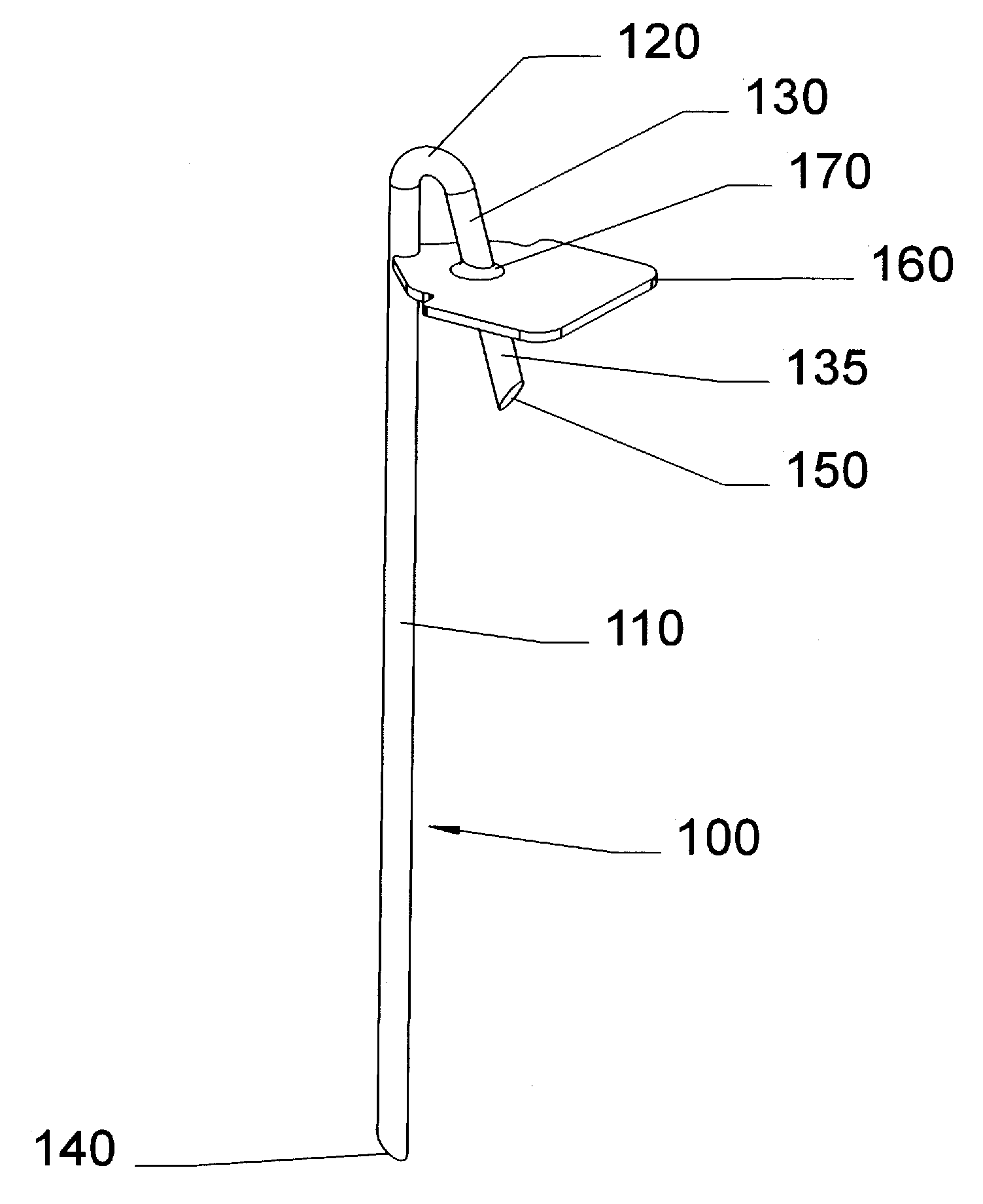
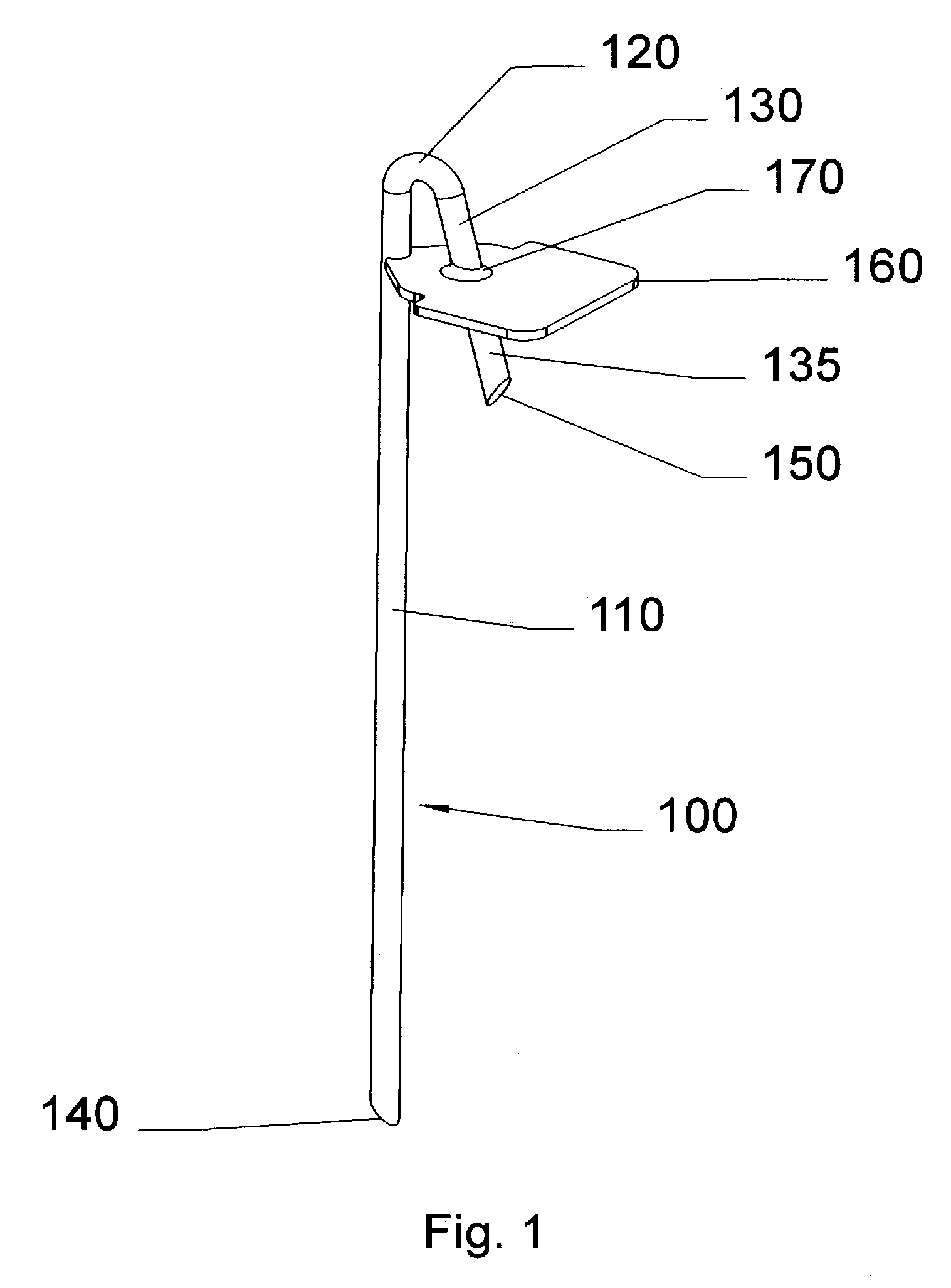
[0155]FIG. 33 shows a single tine embodiment suitable for use as a shore or sand anchor. This embodiment comprises a single tine 3300 with a sharpened tip 140C at the bottom end and a hand or foot plate 3320 at the top end. A plate 160I is attached at the top end of tine 3300, beneath plate 3320. A brace 3340 with a hole 3310 is secured between plate 160I and plate 3320 by a joint or fillet 170B. This embodiment is between 25 cm and 50 cm in length, although any size can be used, depending on the load to be secured to the ground. Plate 3320 is typically between 4 cm and 8 cm in diameter, although other sizes can be used. The cross-section of tine 3300 can be elliptical, round, square, star-shaped, pentagonal, and the like to reduce twisting in the ground during and after installation.

OPERATION—22D EMBODIMENT—FIG. 33

[0156]Tine 3300 is driven into the ground by pressure or blows applied to plate 3320. When fully installed, plate 160I rests firmly on the ground. ...


PUM


Abstract

Ground anchors, in particular tent stakes (100), comprise one or more inherently flexible tines (110), a ground compression plate (160), and various tie points (420, etc.) for attaching a guy rope or the like to the top of anchor. The compression plate extends perpendicularly or at a large angle to the tine so that when the guy rope pulls on the anchor, the tine will tend to rotate about an underground fulcrum so that the compression plate will press against the ground and help the anchor resist pullout. The anchors are driven into the ground with a hammer or mallet. The tie points include hooks (420), closed holes (520), and swivel types comprising vertical members (810) with restraining, bulbous tops (820). An additional spring tie point (1600) can be inserted into optional lugs (1094, 1096) in the compression plate. The stakes can be driven into the ground vertically, or at an angle for additional holding force in some situations. They can also incorporate angled compression plates (160H, 160I). A curved stake (100I) provides additional holding force in sand or friable soils. The stakes can be manufactured by a variety of means in various materials, such as glass-reinforced or other plastics and forged or stamped metals.

Description

CROSS-REFERENCE TO RELATED APPLICATIONS[0001]This application is a continuation-in-part (CIP) of application Ser. No. 11 / 129,177, filed 13 May 2005, now abandoned, and application Ser. No. 10 / 989,960, Filed 15 Nov. 2004, also abandoned. Application Ser. No. 10 / 989,960 is a (CIP) of application Ser. No. 08 / 923,443, Filed 4 Sep. 1997, now abandoned. Application Ser. No. 08 / 923,443 claims priority of Australian application Ser. No. 36,761 / 97, filed 4 Sep. 1996.BACKGROUND[0002]1. Field of Invention[0003]This invention relates generally to ground anchors and in particular to tent pegs or stakes that are used to anchor tents and guy ropes to the ground and to ground or mooring anchors for recreational watercraft, off-road vehicles, and light aircraft.[0004]2. Prior-Art—Tent Stakes[0005]Prior-art tent and guy rope stakes have generally taken the shape of large nails or pegs. They normally secure a tent at two or more places. Some hold the edges of the tent against the ground, and others an...

Claims


Application Information

Patent Timeline
Patent Type & Authority Patents(United States)
IPC IPC(8): B63B21/24E02D5/74
CPCE04H15/62
Inventor BURNS, PETER ROBERT
Owner BURNS PETER ROBERT
Why Eureka
Try Eureka