
Projection type display apparatus

a display device and projection type technology, applied in the direction of printers, instruments, camera focusing arrangement, etc., can solve the problems of high projector cost and high cost in either direction, and achieve the effect of simple processing circuit and cost reduction

Inactive Publication Date: 2007-12-04
CANON KK
View PDF2 Cites 38 Cited by
  • Summary
  • Abstract
  • Description
  • Claims
  • Application Information

AI Technical Summary

Benefits of technology

The present invention provides a projection type display apparatus with a simple processing circuit and cost reduction. The apparatus includes a projection portion for projecting an image onto a surface, a light receiving portion for detecting a reference image projected onto the surface, and a scanning portion for scanning the reference image in a direction of a base line length. The apparatus performs focusing based on information about the scanning position of the reference image upon predetermined detection with the light receiving portion. The light receiving portion includes a single-cell or two-cell photosensor, and the apparatus performs focusing based on information about the scanning position of the reference image for situations where signals detected by the photosensor have maximum or substantially the same intensity. The apparatus also includes an amplifying portion for amplifying a signal detected by the light receiving portion. The technical effects of the invention include improved image quality, reduced cost, and improved user experience.

Problems solved by technology

H09-197249 requires, however, complicated signal processing where a line sensor is used to receive light of a reference image, and its position on the line sensor is determined by calculation through signal processing.
Besides, such a projector costs high because the line sensor itself is expensive.
H09-197249 necessitates any mechanical mechanism and involves high costs either way.

Method used


Image

  • Projection type display apparatus
  • Projection type display apparatus
  • Projection type display apparatus

Examples


Embodiment Construction

[0026]Hereinafter, preferred embodiments of the present invention will be described. Prior to detailed explanation thereof, a basic concept of the present invention is described first.

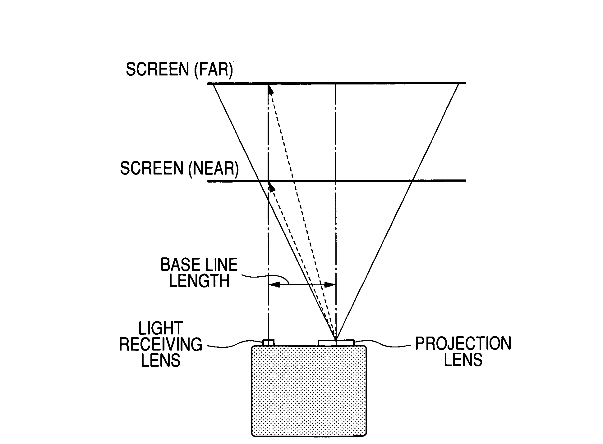
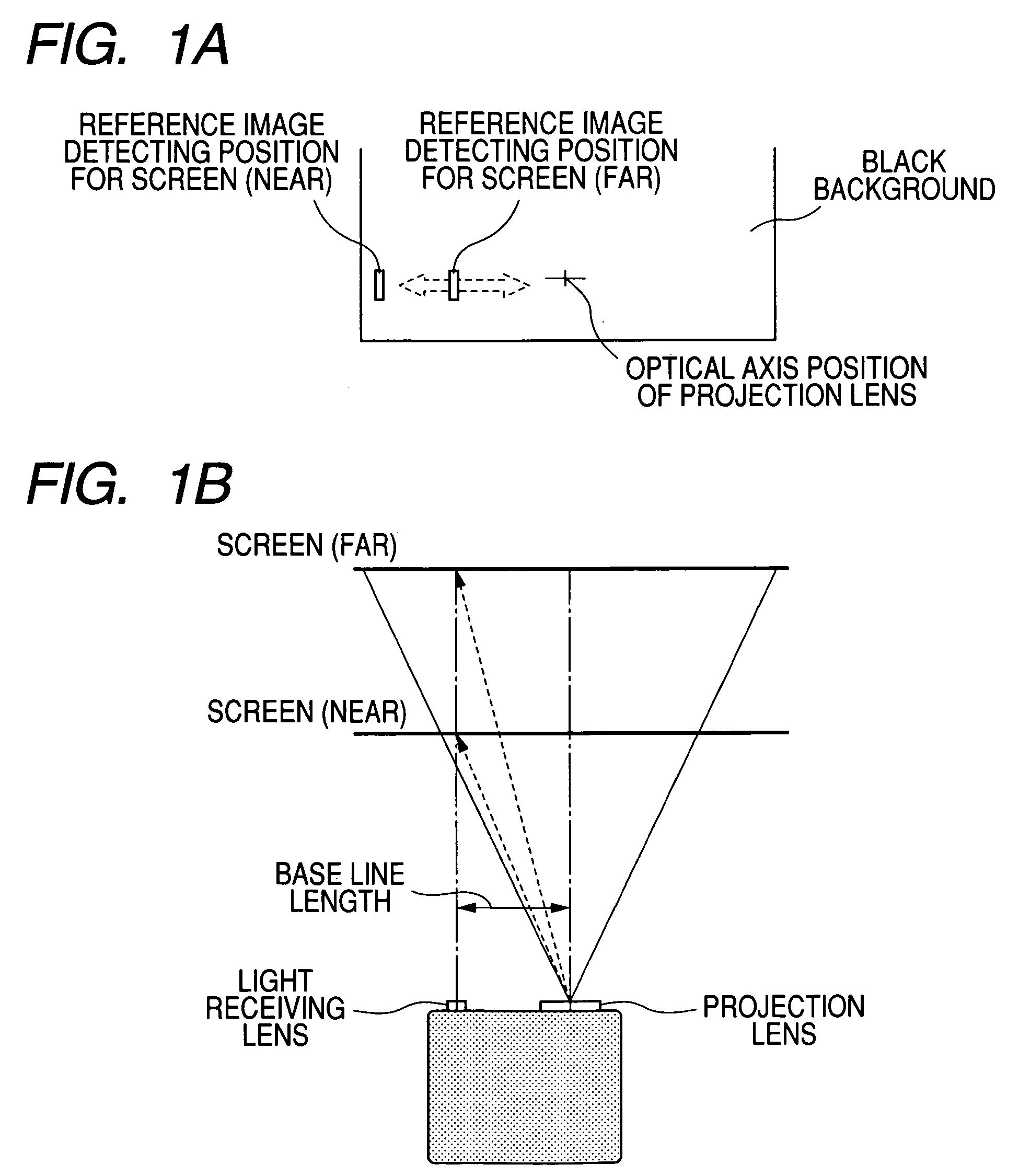
[0027]FIGS. 1A and 1B illustrate the principle indicative of a basic concept of the present invention. The present invention is based on a so-called active triangulation principle employed for an image-taking device etc. FIGS. 1A and 1B are given to illustrate the principle. In the image taking device etc., an infrared LED or the like is generally used to apply reference spot image to a subject, and the reflected light is received by a photodiode, a CCD sensor, or the like, and the distance to the subject is calculated from a displacement of a detecting position, due to the parallax.

[0028]Here, active distance-measuring methods are classified into two types. One is a method in which scanning is performed in a light projection side and detecting a peak position by a fixed light receiving sensor. The oth...


PUM


Abstract

A projection type display apparatus includes a projection portion for projecting an image onto a surface to be projected, a light receiving portion disposed apart from the projection portion by a base line length and used for detecting a reference image projected onto the surface to be projected, and a scanning portion for scanning the reference image on the surface to be projected in a direction of the base line length, in which the projection portion is focused based on information about a scanning position of the reference image upon predetermined detection with the light receiving portion. With the projection type display apparatus, a system can be configured with a simple processing circuit, and cost reduction can be realized.

Description

BACKGROUND OF THE INVENTION[0001]1. Field of the Invention[0002]The present invention relates to a projection type display apparatus (transmission type liquid crystal projector, reflection type liquid crystal projector, or the like). In particular, the invention relates to an automatic focusing device of a front projector.[0003]2. Related Background Art[0004]Some proposals have been made hitherto on a focusing method used for a projection optical system in a projection type display apparatus (hereinafter referred to as projector).[0005]Japanese Patent Application Laid-Open No. H09-197249 discloses this kind of projector having a structure in which a focusing operation is performed such that a reference image is projected onto substantially the center of a projection area on a screen surface by projection optical means, and light reflected by the surface is allowed to pass through a slit and received by a line sensor, and then a position of the light incident on the line sensor is de...

Claims


Application Information

Patent Timeline
Patent Type & Authority Patents(United States)
IPC IPC(8): G03B21/00G03B3/00G02B7/28G02B7/32G03B21/14
CPCG02B26/101G03B21/53G03B21/26
Inventor FUJIWARA, AKIHIRO
Owner CANON KK
Learn More