Power switchover apparatus for a hybrid vehicle

a hybrid vehicle and power switch technology, applied in the direction of electric control, machines/engines, cycles, etc., can solve the problems of sudden change of driving torque of the vehicle, short cruising distance of electric automobiles, and shock of switchover, so as to achieve smooth power switchover and not increase in weight. , the effect of not increasing very much

Active Publication Date: 2007-12-04
HONDA MOTOR CO LTD
View PDF12 Cites 19 Cited by
  • Summary
  • Abstract
  • Description
  • Claims
  • Application Information

AI Technical Summary

Benefits of technology

[0011]It is an object of the present invention to provide a power switchover apparatus for a hybrid vehicle that solves the disadvantages of the background art described above and can perform power switchover smoothly with a configuration which is simple and not increased very much in weight.

Problems solved by technology

However, presently, the cruising distance of an electric automobile is sometimes short due to a limitation in capacity of the batteries.
However, if the torque of the engine is added simply to the torque of the motor upon such power switchover, then the driving torque of the vehicle changes suddenly and a switchover shock occurs.
Also when the rotational speeds of the engine and the motor do not coincide with each other, the driving torque of the vehicle changes suddenly and a switchover shock occurs similarly.
Therefore, the background art described above has a configuration that is complicated and a weight that is increased.

Method used


Image

  • Power switchover apparatus for a hybrid vehicle
  • Power switchover apparatus for a hybrid vehicle
  • Power switchover apparatus for a hybrid vehicle

Examples


first embodiment

[0072]FIG. 5 is a flow chart illustrating a procedure of the power switchover method, and FIG. 6 is a timing chart of the procedure.

[0073]At step S1, the traveling state of the vehicle is determined based on results of detection of the vehicle speed V, engine rotational speed Ne, throttle opening θth, and so forth. At step S2, it is determined based on the traveling state whether or not a power switchover condition for switching over the power source from the drive motor 21b to the engine 20 is satisfied. If such a power switchover condition is satisfied, that is, if the throttle opening θth is higher than a reference opening and the vehicle speed V and the engine rotational speed Ne exhibit an increasing tendency, then the processing advances to step S3.

[0074]At step S3, a target engine rotational speed (target Ne) upon power switchover is calculated by the target rotational speed determination section 7a based on the vehicle speed V and the throttle opening θth at present. At step...

second embodiment

[0078]FIG. 7 is a flow chart of a power switchover method according to the present invention, and FIG. 8 is a timing chart of the power switching method.

[0079]At step S1, the traveling state of the vehicle is determined based on results of detection of the vehicle speed V, engine rotational speed Ne, throttle opening θth, and so forth. At step S2, it is determined based on the traveling state whether or not a power switchover condition for switching over the power source from the drive motor 21b to the engine 20 is satisfied. If such a power switchover condition is satisfied, that is, the throttle opening θth is higher than a reference opening and the vehicle speed V and the engine rotational speed Ne exhibit an increasing tendency, then the processing advances to step S3.

[0080]At step S3, a target engine rotational speed (target Ne) upon power switchover is calculated by the target rotational speed determination section 7a based on the vehicle speed V and the throttle opening θth a...

third embodiment

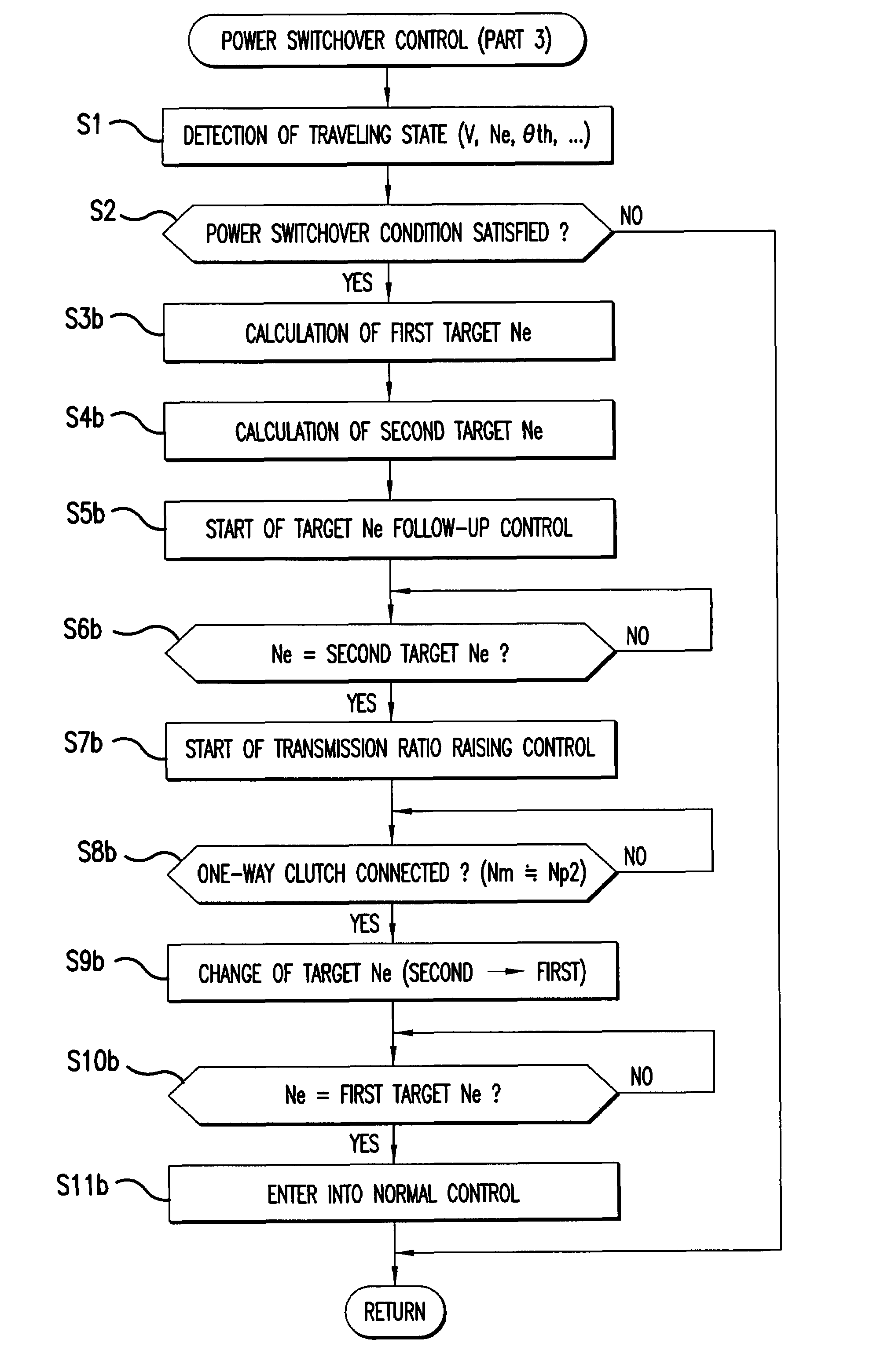
[0084]FIG. 9 is a flow chart of a power switchover method according to the present invention, and FIG. 10 is a timing chart of the power switching method.

[0085]At step S1, the traveling state of the vehicle is determined based on results of detection of the vehicle speed V, engine rotational speed Ne, throttle opening θth, and so forth. At step S2, it is determined based on the traveling state whether or not a power switchover condition for switching over the power source from the drive motor 21b to the engine 20 is satisfied. If such a power switchover condition is satisfied, that is, the throttle opening θth is higher than a reference opening and the vehicle speed V and the engine rotational speed Ne exhibit an increasing tendency, then the processing advances to step S3b.

[0086]At step S3b, a target engine rotational speed (first target Ne) upon power switchover is calculated by the target rotational speed determination section 7a based on the vehicle speed V and the throttle ope...


PUM


Abstract

To provide a power switchover apparatus for a hybrid vehicle, which can perform power switchover smoothly. Target follow-up control is started, and when the engine speed reaches a clutch-in speed of a starter clutch, the input power shaft of a continuously variable transmission starts rotation. The speed of the output power shaft also begins to gradually rise in response to the starting of rotation. The engine speed then reaches a target, and transmission ratio raising control of raising the transmission ratio based on the difference between the motor speed of a drive shaft and the speed of a driven side pulley is started. The motor speed Nm of the drive motor and the speed of the driven side power transmission pulley then become equal to each other and the one-way clutch is placed into a connected state. Consequently, the transmission ratio raising control is stopped and normal control is entered.

Description

CROSS-REFERENCE TO RELATED APPLICATIONS[0001]This nonprovisional application claims priority under 35 U.S.C. § 119(a) on Patent Application No. 2004-229414, filed in Japan on Aug. 5, 2004, the entirety of which is incorporated herein by reference.BACKGROUND OF THE INVENTION[0002]1. Field of the Invention[0003]This invention relates to a power switchover apparatus for switching over the power source from a motor to an engine in a hybrid vehicle of the parallel type or the parallel and serial combined type wherein a drive shaft of the engine and a drive shaft of the motor are mechanically connected to each other.[0004]2. Description of Background Art[0005]An electric automobile using a motor as a power source provides no atmospheric pollution and low noise pollution and is high in acceleration and deceleration when compared with a conventional automobile, which uses an engine as a power source. However, presently, the cruising distance of an electric automobile is sometimes short due ...

Claims


Application Information

Patent Timeline
Patent Type & Authority Patents(United States)
IPC IPC(8): B60W10/04B60W10/10B60L50/11B60K6/36B60K6/383B60K6/48B60K6/543B60K17/04B60L50/15B60L50/16B60W10/06B60W10/101B60W10/105B60W10/107B60W20/00B62M23/02F02D29/00F02D29/02F02D41/04F02D41/14F16H59/38F16H59/56F16H61/02F16H61/66F16H61/662
CPCB60K6/383B60K6/485B60K6/543B60W10/06B60W10/08B60W10/10B60W20/00B62M7/12B62M23/02B60K6/405Y10T477/6403B60L2200/12B60Y2200/12B60Y2200/126B62K2202/00Y02T10/6226Y02T10/6286Y10S903/93Y10T477/26B60L50/15Y02T10/62Y02T10/7072B60W10/02B60W20/30
Inventor UCHISASAI, HIROAKITSUKADA, YOSHIAKIKOJIMA, HIROYUKIOZEKI, TAKASHINAKAMURA, KAZUHIKO
Owner HONDA MOTOR CO LTD
Why Eureka
Try Eureka