Cable support assembly for minimizing bend radius of cables

a cable support and cable technology, applied in the direction of cables, insulated conductors, conductors, etc., can solve the problems of affecting the data transmission rate, sagging of cables in the open spaces between the support elements, and sagging of conductors within the cables, so as to facilitate the release of cable tray sections

Active Publication Date: 2007-12-04
ARLINGTON INDS
View PDF8 Cites 30 Cited by
  • Summary
  • Abstract
  • Description
  • Claims
  • Application Information

AI Technical Summary

Benefits of technology

[0009](3) The cable brackets include a latching mechanism that enable the cable tray sections to be securely latched into position after brackets are aligned and installed.
[0010](4) The latching mechanism facilitates easy release of the cable tray sections for inspection or repair of existing cables or easy installation of additional cables.
[0011](5) The latching mechanism enables lowering of one side of the cable tray when released. As a result the c

Problems solved by technology

Routing electrical cables in this manner causes each cable to be supported by the narrow thickness of the support element and will lead to sagging of cables in the open spaces between the support elements.
Unfortunately, for the installation of low voltage cables such as communic

Method used


Image

  • Cable support assembly for minimizing bend radius of cables
  • Cable support assembly for minimizing bend radius of cables
  • Cable support assembly for minimizing bend radius of cables

Examples


Embodiment Construction

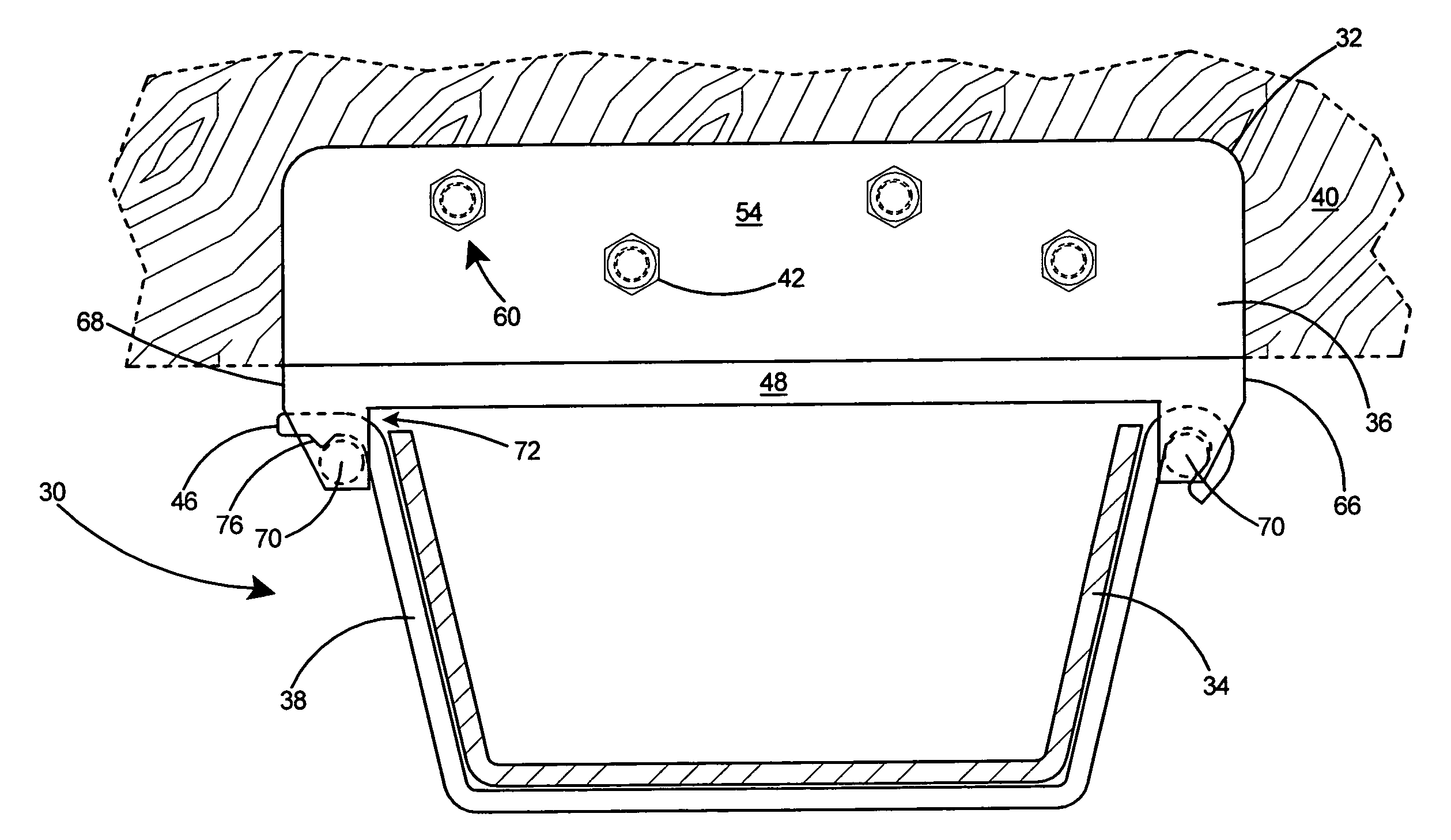
[0081]With reference to FIG. 16 there is shown a preferred embodiment of a cable support assembly 30, which includes a bracket 32 and an elongated cable tray 34. The bracket 32 includes a base member 36 and a hinge arm 38. The bracket 32 is shown in FIG. 16 secured to a building structure 40 by fasteners 42.

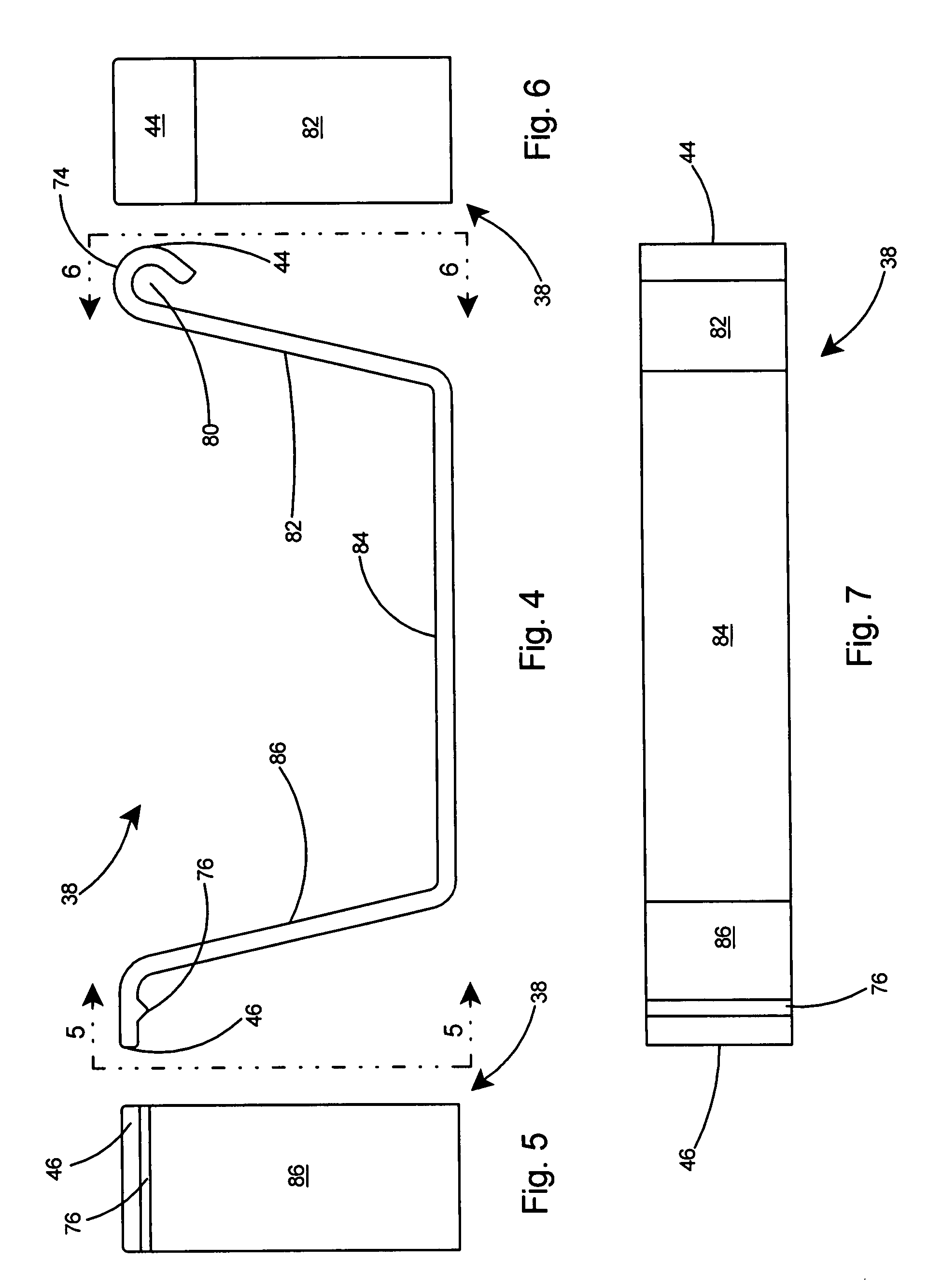
[0082]As shown in FIG. 15, the hinge arm 38 is pivotally attached at a first end 44 to the base member 36. The hinge arm 38 further includes a second end 46 adapted to latch to the base member 36.

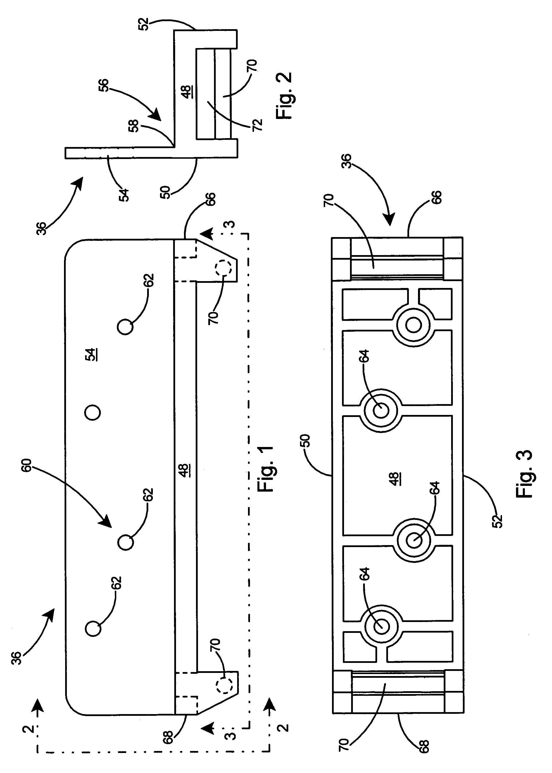
[0083]Referring to FIGS. 1-3, the base member 36 includes a horizontal support member 48 having a first 50 and second side 52. An integral flange member 54 extends upwardly from the first side 50 of the horizontal support member 48. A seat 56 is defined by the juncture 58 of the horizontal support member 48 and the integral flange 54. The base member 36 includes an attachment arrangement 60 for securing the bracket to a building structure (not shown). The attachment arrangement 60 includ...


PUM


Abstract

A cable support assembly for routing electrical, communication, or data cables throughout a building. The cable support assembly includes cable trays and brackets for securing the cable trays to an overhead structure. Tray couplers are provided for coupling trays together. The brackets include a base member and a hinge arm pivotally attached to the base member. The brackets are first secured to the overhead structure to establish a desired path for the cables. The hinge arms on the installed brackets are pivoted downwards and a cable tray section inserted therein. The hinge arms and cable tray sections may be rotated upwards and latched to the base members to lock the cable trays in place. Adjacent cable trays may be joined with couplers to create a cable support assembly in which the cable tray provides support for any electrical, communication, or data cables installed therein.

Description

FIELD OF THE INVENTION[0001]This invention relates to cable supports and specifically to a cable support assembly or cable raceway that supports electrical cables in such a manner that the bend radius of individual cables is minimized.BACKGROUND OF THE INVENTION[0002]The installation of electrical cables in buildings is typically accomplished by drilling holes in wooden support elements such as joists or studs or using existing holes in metal support elements and routing the cables through the holes. Routing electrical cables in this manner causes each cable to be supported by the narrow thickness of the support element and will lead to sagging of cables in the open spaces between the support elements. Unfortunately, for the installation of low voltage cables such as communication or database cables, sagging can disturb the conductors within the cables. Bending and twisting of conductors can adversely affect the data transmission rate, which becomes very critical in cables having hi...

Claims


Application Information

Patent Timeline
IPC IPC(8): H02G3/04
CPCH02G3/32H02G3/0608
Inventor GRETZ, THOMAS J.
Owner ARLINGTON INDS
Why Eureka
Try Eureka