Systems and methods for non-destructive mass sensing

Active Publication Date: 2007-12-04
NOVARTIS AG
View PDF28 Cites 6 Cited by
  • Summary
  • Abstract
  • Description
  • Claims
  • Application Information

AI Technical Summary

Benefits of technology

[0008]In one aspect, the substance is volumetrically metered prior to applying the energy. For example, the substance may comprise a powder that is metered by depositing

Problems solved by technology

In some cases, the transmitted or emitted light may create an interference pattern with the light being directed onto the substance.

Method used


Image

  • Systems and methods for non-destructive mass sensing
  • Systems and methods for non-destructive mass sensing
  • Systems and methods for non-destructive mass sensing

Examples


example

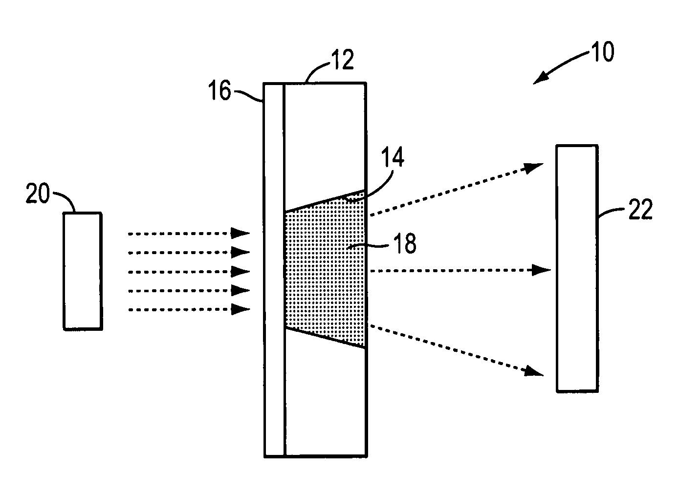
[0066]The following is one non-limiting example of a technique that may be employed to determine a relationship between light transmitted through powder pucks and their associated masses. In this example, a system similar to the system of FIG. 3 (without the use of filter 16) was employed. Initially, a powder puck was manually placed into a metering chamber of fixed volume within a change tool. The change tool was held horizontally such that the wide portion of the metering chamber faced upwards. Powder was introduced into the metering chamber with a spatula while a slight vacuum was applied to the back of the metering chamber. The vacuum served to compress the powder into a formed puck.

[0067]After forming the puck, the change tool was placed in a rigid fixture. A laser (630 nm, 5 mW, Coherent) was positioned so that its beam was perpendicular with the change tool and was centered on the metering chamber. The laser beam cross section was essentially circular and of sufficient diamet...


PUM


Abstract

The invention provides systems and methods for measuring the mass of a substance. In one method, energy is applied to a substance and a response resulting from the application of energy as measured. The mass of the substance is then determined based at least in part on the measured response.

Description

CROSS REFERENCE TO RELATED APPLICATIONS[0001]This application is a continuation-in-part application and claims the benefit of U.S. Provisional Application No. 60 / 172,316, filed Dec. 17, 1999, the complete disclosure of which is incorporated by reference.BACKGROUND OF THE INVENTION[0002]This invention relates generally to the field of measuring, and in particular to the field of mass measurement. More specifically, the invention relates to techniques for measuring the mass of a substance that has been volumetrically metered.[0003]In many fields, there is a need to precisely measure the mass of a substance. For example, substances such as drugs, chemicals, and the like may often need to have their mass measured. For instance, drugs are often prescribed in terms of unit dosages that are often determined based on the mass of the drug formulation. Therefore, the mass of the drug formulation contained in such unit dosages needs to be measured.[0004]A traditional way to measure the mass of...

Claims


Application Information

Patent Timeline
IPC IPC(8): G01B11/14G01G3/12G01G9/00
CPCG01G9/005G01G3/125
Inventor NANTEL, NORMANDSMITH, ADRIANCHEU, SCOTPARKS, DERRICK J.GHANDI, JAMSHED
Owner NOVARTIS AG
Why Eureka
Try Eureka