Check patentability & draft patents in minutes with Patsnap Eureka AI!

Methods and systems for three-dimensional motion control and tracking of a mechanically unattached magnetic probe

Inactive Publication Date: 2007-12-04
THE UNIV OF NORTH CAROLINA AT CHAPEL HILL
View PDF11 Cites 13 Cited by
  • Summary
  • Abstract
  • Description
  • Claims
  • Application Information

AI Technical Summary

Benefits of technology

[0009]According to one aspect of the invention a plurality of magnetic poles are geometrically arranged with respect to each other and with respect to a magnetic probe for applying magnetic force to the probe and controlling motion of the probe in three dimensions. At least one magnetizing coil is coupled to the magnetic poles for generating the magnetic force on the probe through the poles. An optical tracker tracks the position of the probe in three dimensions while the probe is moving in three dimensions. A controller measures the error between the position of the probe and a position control signal and energizes the coils to move the probe in three dimensions and minimize the error.
[0010]Because the methods and systems of the present invention are capable of simultaneously controlling the motion of and tracking a magnetic probe in three dimensions, the mechanical properties of structures within enclosed and other hard-to-reach environments can be determined with minimal disturbance of the environments.
[0012]It is another object of the invention to provide methods and systems for magnetically controlling motion of and optically tracking a mechanically unattached magnetic probe in three dimensions that reduce the disturbance of the system under test.

Problems solved by technology

As a result, conventional atomic force microscopy is unsuitable for measuring mechanical properties of structures within enclosed regions, such as organelles within a cell membrane, or the other structures that are inaccessible for scanning with a mechanically attached probe.
However, once the probe is mechanically decoupled from the remainder of the system, tracking and controlling movement of the probe become problematic.
One known technique of applying force to a mechanically decoupled probe is referred to as “optical tweezers.” This technique requires high optical field intensities that interact strongly with many materials and may produce undesirable side effects on experiments in biological systems.

Method used


Image

  • Methods and systems for three-dimensional motion control and tracking of a mechanically unattached magnetic probe
  • Methods and systems for three-dimensional motion control and tracking of a mechanically unattached magnetic probe
  • Methods and systems for three-dimensional motion control and tracking of a mechanically unattached magnetic probe

Examples


Embodiment Construction

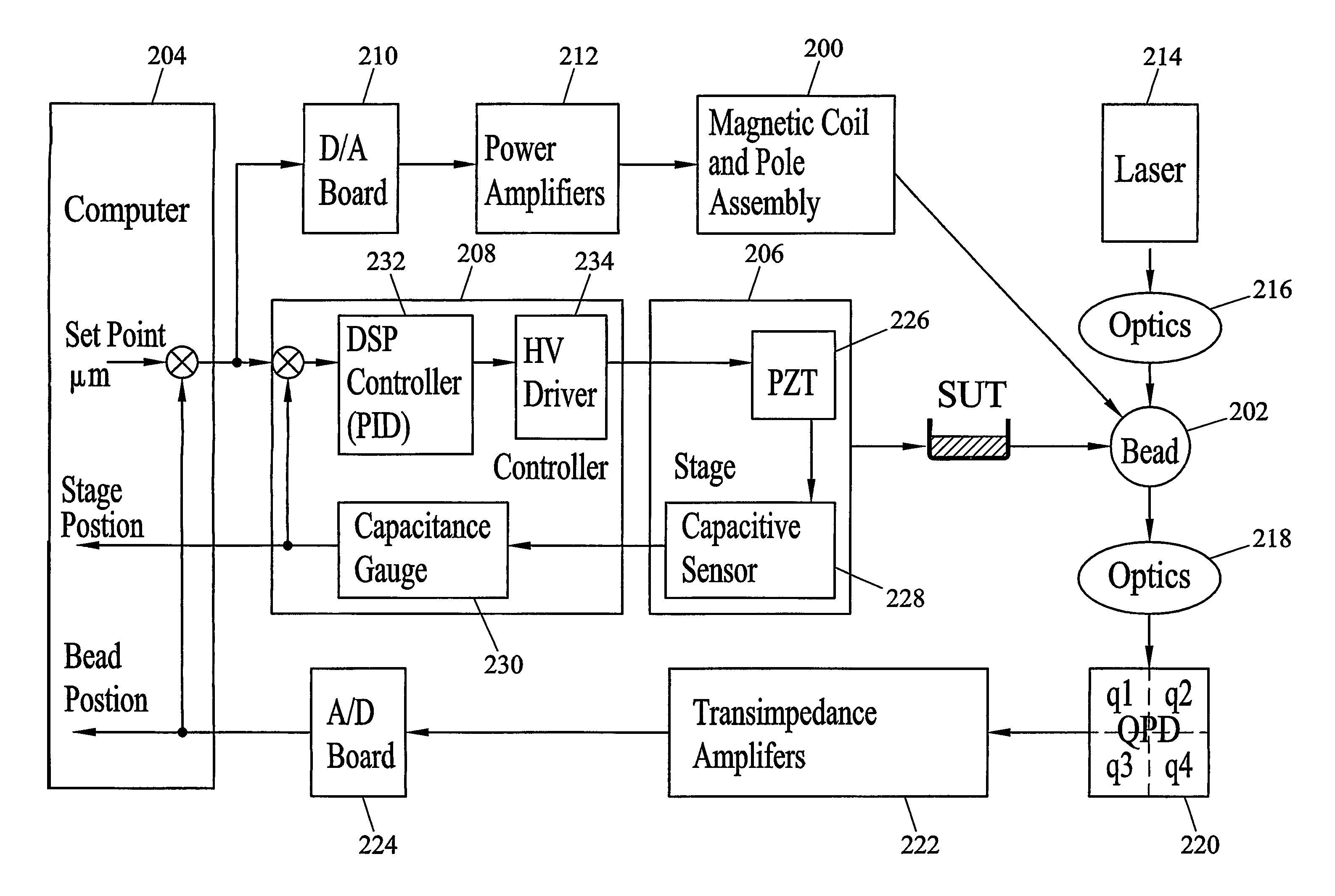
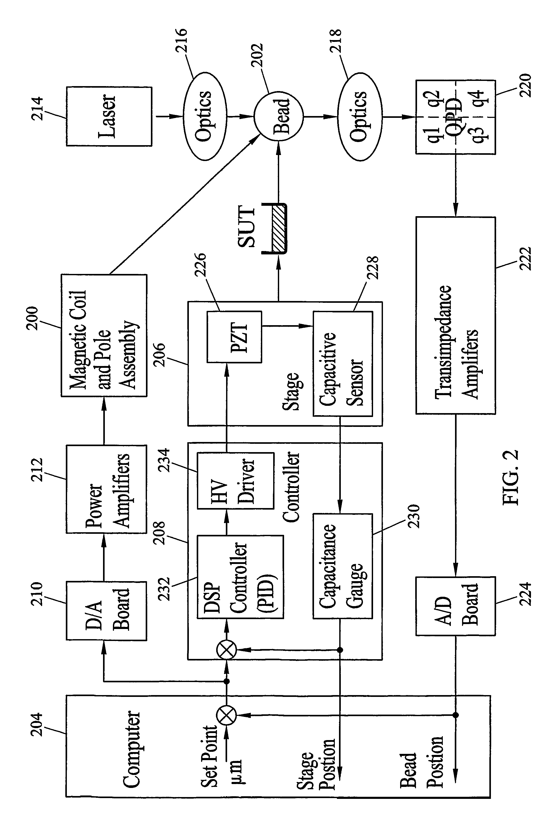
[0031]The methods and systems for three-dimensional motion control and tracking of a mechanically unattached magnetic probe according to embodiments of the present invention are particularly well suited for 3D force microscopy. FIG. 2 illustrates exemplary components of a system for three-dimensional motion control and tracking of a mechanically unattached magnetic probe in a 3D force microscopy application according to an embodiment of the present invention. Referring to FIG. 2, the system includes magnetic coil and pole assembly 200 for controlling the position of a mechanically unattached magnetic bead or probe 202. The magnetic force supplied by assembly 200 is controlled by a computer 204. More particularly, computer 204 receives as inputs a desired position set point, measured bead position, and position of a stage 206. Computer 204 implements a control algorithm that selects the poles that should be magnetized and the corresponding magnetizing currents to minimize the error b...


PUM


Abstract

Methods and systems for controlling motion of and optically tracking a mechanically unattached probe (202) in three-dimensions are disclosed. A mechanically unattached magnetic probe (202) is placed in the system under test. The position of the probe is optically tracked in three dimensions by sensing light scattered by the probe and direct light from a light source. Magnetic poles (200) positioned about the probe are selectively magnetized to control motion of the probe in three dimensions by minimizing error between a sensed position and a desired position. In one implementation, the coil currents are time division multiplexed such that the average force on the probe produces motion in a desired direction.

Description

PRIORITY APPLICATIONS[0001]This application claims the benefit of U.S. Provisional Patent Application No. 60 / 326,530, filed Sep. 28, 2001, the disclosure of which is incorporated herein by reference in its entirety.GRANT STATEMENT[0002]This work was supported by NIH Grant Number P41 RR02170-17. Thus, the U.S. Government has certain rights to this invention.TECHNICAL FIELD[0003]The present invention relates to methods and systems for three-dimensional motion control and tracking of a mechanically unattached probe. More particularly, the present invention relates to methods and systems for magnetically controlling the motion of a mechanically unattached probe in three dimensions while optically tracking the probe in three dimensions.BACKGROUND ART[0004]In the field of scanning probe microscopy, small probes interact with systems under test to measure mechanical properties of the systems under test. For example, in atomic force microscopy, a small probe (typically sub-micrometer sized)...

Claims


Application Information

Patent Timeline
IPC IPC(8): G01C9/00G01Q10/06G01Q60/50
CPCG01Q10/06B82Y35/00B82Y15/00
Inventor VICCI, LEANDRASUPERFINE, RICHARD
Owner THE UNIV OF NORTH CAROLINA AT CHAPEL HILL
Features
  • R&D
  • Intellectual Property
  • Life Sciences
  • Materials
  • Tech Scout
  • Unparalleled Data Quality
  • Higher Quality Content
  • 60% Fewer Hallucinations
Learn More