Disk drive input sequencing for staggered drive spin-up

a technology of drive spin-up and input sequencing, applied in the field of disk drives, can solve the problems of disk drive delay in spinning up, and achieve the effects of reducing system peak power requirements, saving space, thermal budget, and cost in storage systems

Active Publication Date: 2007-12-04
EMC IP HLDG CO LLC
View PDF16 Cites 75 Cited by
  • Summary
  • Abstract
  • Description
  • Claims
  • Application Information

AI Technical Summary

Benefits of technology

[0010]The various aspects of the invention are used to cause the multiple disk drives in a system to spin up at differen...

Problems solved by technology

The 5V input controls the disk drive communications electronics; thus, delaying...

Method used


Image

  • Disk drive input sequencing for staggered drive spin-up
  • Disk drive input sequencing for staggered drive spin-up
  • Disk drive input sequencing for staggered drive spin-up

Examples


Embodiment Construction

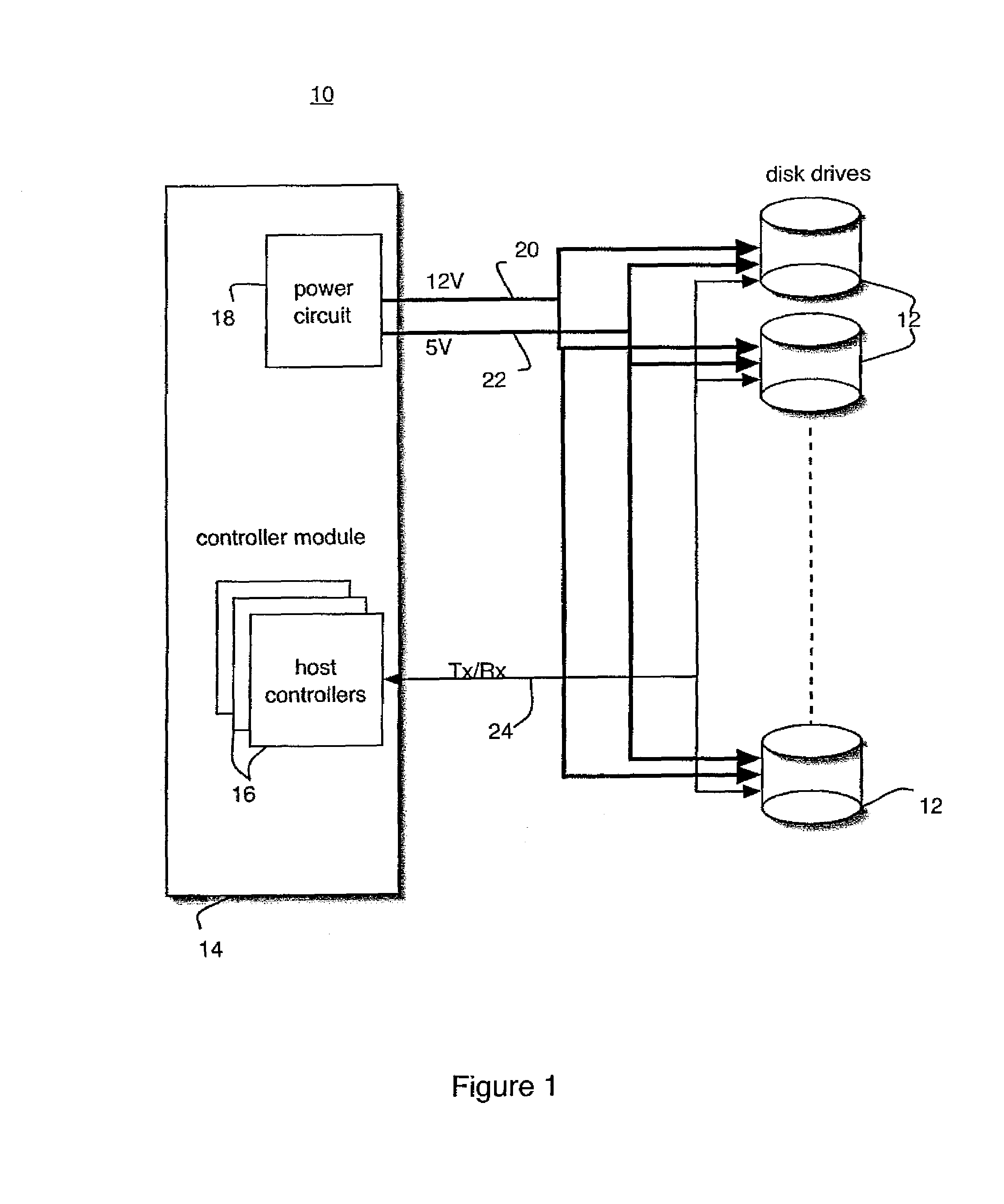
[0019]Referring to FIG. 1, there is shown a storage system 10 that is one of many types of systems in which the principles of the invention may be employed. The storage system 10 includes multiple disk drives 12 coupled to a controller module 14. The controller module 14 includes one or more host controllers 16 and power circuit 18. The power circuit 18 provides two different voltages, for example 12 Volt (12V) power 20 and 5 Volt (5V) power 22, to the disk drives 12. The disk drives 12 use the different voltages for specific purposes. For example, the 12V power 20 may be used to power the mechanical parts of the rotation drives, while the 5V power 22 can be used to power on-board electronics. It is understood that other voltage values can be used without departing from the principles of the invention. For example, some drives may power their logic using 3.3V power.

[0020]The host controllers 16 and disk drives 12 communicate via communications signals 24, and in the case shown parti...


PUM


Abstract

Disk drive spin-up is staggered to reduce peak power requirements. Spin-up of the drives is controlled by selectively delaying voltage inputs to the disk drives. Alternately, spin-up of the drives is controlled by staggering the timing of communications to the disk drives.

Description

FIELD OF THE INVENTION[0001]The present invention relates generally to disk drives and more particularly to controlling disk drive spin-ups in a multi-drive environment.BACKGROUND OF THE INVENTION[0002]As storage technologies advance, disk drives continue to become faster and cheaper. As costs come down, computing, storage, and networking systems incorporate greater numbers of disk drives to maximize storage space and performance. As the numbers of drives in a system increases, power budgets must be adjusted.[0003]Current disk drives, such as hard disk drives and CD drives, rely on mechanically rotating disks for storage of information. During operation, the disks rotate at very high rates of speed. Upon power-up and initialization, 3-4 times more current can be required to accelerate the rotation of the disk—or “spin up” the disk. In systems containing many such disks, a large amount of power is required upon power-up and initialization to spin up the disks. However, this large amo...

Claims


Application Information

Patent Timeline
IPC IPC(8): G06F1/26
CPCG06F1/26G11B19/209G11B19/2054
Inventor BURROUGHS, JOHN V.STRICKLAND, STEPHEN E.DORR, TIMOTHY E.
Owner EMC IP HLDG CO LLC
Why Eureka
Try Eureka