Sinuous chevron exhaust nozzle

a chevron and exhaust nozzle technology, applied in the direction of machines/engines, power plant exhaust arrangements, jet propulsion plants, etc., can solve the problems of substantial noise, substantial noise attenuation, and noise attenuation comes with a corresponding price, so as to reduce fuel consumption during operation and improve performance.

Active Publication Date: 2007-12-11
GENERAL ELECTRIC CO
View PDF45 Cites 101 Cited by
  • Summary
  • Abstract
  • Description
  • Claims
  • Application Information

AI Technical Summary

Problems solved by technology

The high velocity jets interact with each other as well as with the ambient air and produce substantial noise along the take-off path of the aircraft.
In a typical turbofan engine application, the chevron exhaust nozzle replaces the otherwise simple annular core exhaust nozzle and effects substantial noise attenuation as the core exhaust gases mix with the fan exhaust flow channeled thereover during operation.
However, noise attenuation comes with a corresponding price.
In particular, the chevron exhaust nozzle introduces additional pressure losses in the exhaust flows being mixed thereby which decreases the overall efficiency or performance of the engine.

Method used


Image

  • Sinuous chevron exhaust nozzle
  • Sinuous chevron exhaust nozzle
  • Sinuous chevron exhaust nozzle

Examples


Embodiment Construction

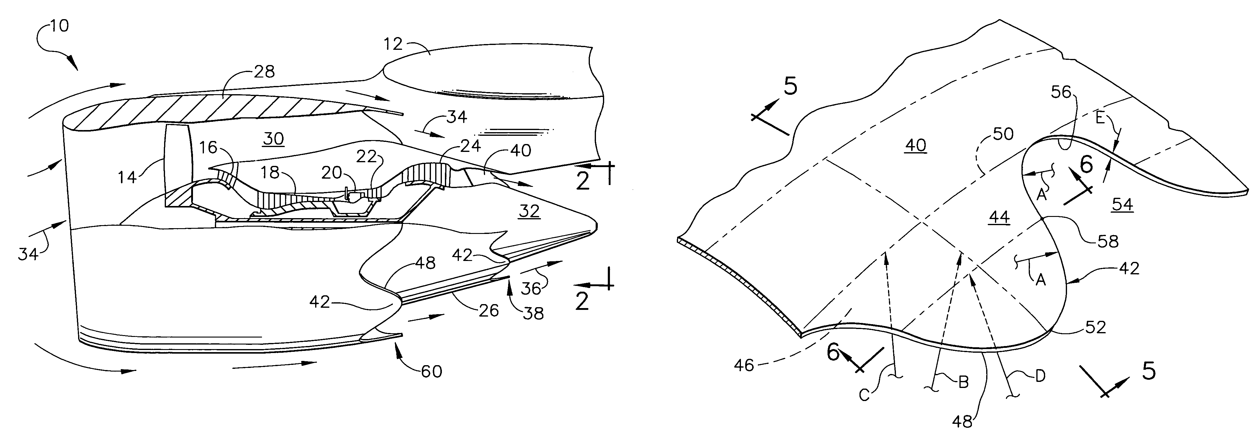
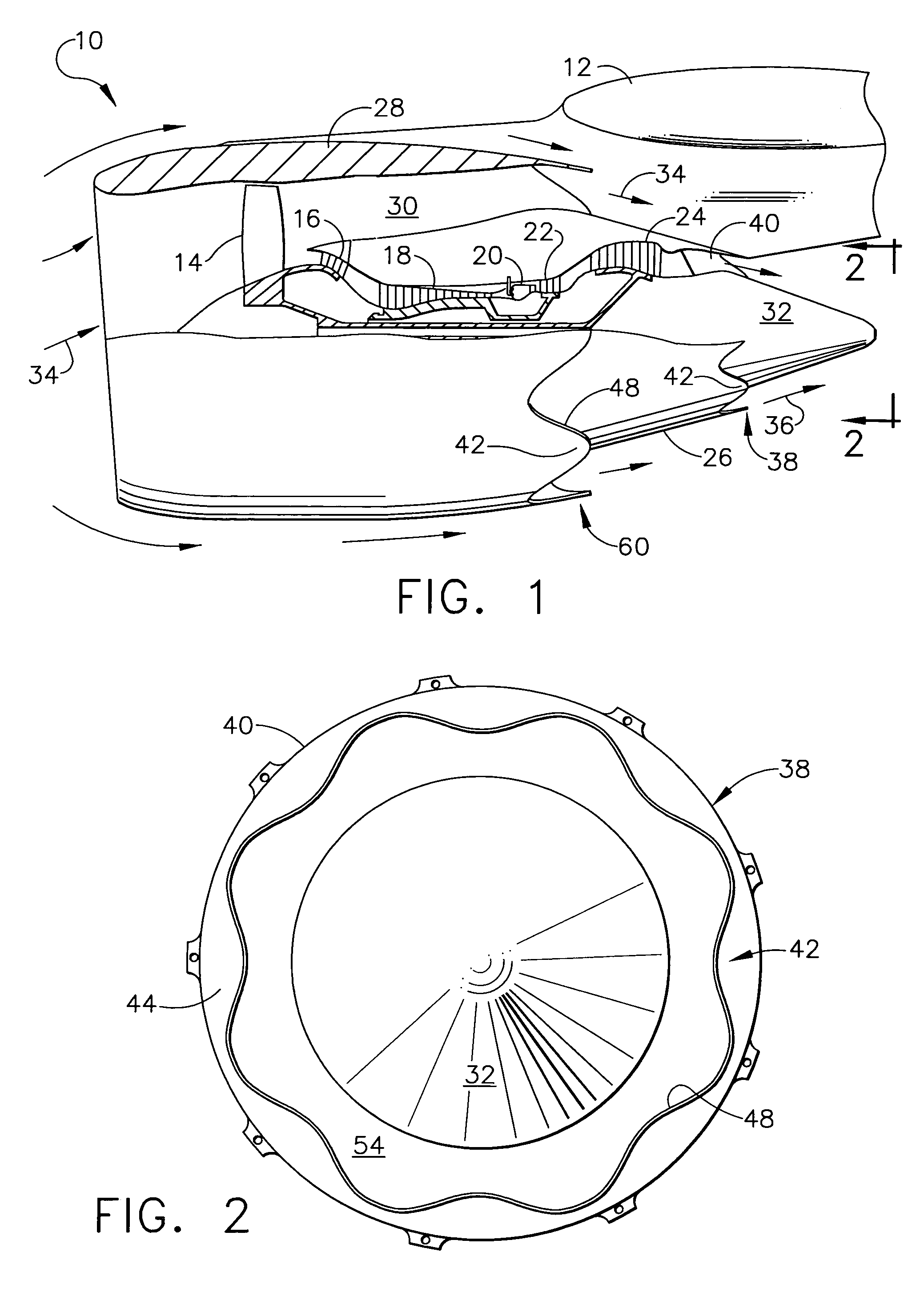
[0017]FIG. 1 illustrates an aircraft turbofan gas turbine engine 10 suitably joined to a wing of an aircraft 12 illustrated in part. The engine includes in serial flow communication a fan 14, low pressure compressor 16, high pressure compressor 18, combustor 20, high pressure turbine (HPT) 22, and low pressure turbine (LPT) 24 operatively joined together in a conventional configuration.

[0018]The engine also includes a core nacelle or cowl 26 surrounding the core engine and LPT, and a fan nacelle or cowl 28 surrounding the fan and the forward part of the core cowl and spaced radially outwardly therefrom to define a bypass duct 30. A conventional centerbody or plug 32 extends aft from the LPT and is spaced radially inwardly from the aft end of the core cowl.

[0019]During operation, ambient air 34 flows into the fan 14 as well as around the fan cowl. The air is pressurized by the fan and discharged through the fan duct as fan exhaust for producing thrust. A portion of the air channeled ...


PUM


Abstract

A gas turbine engine exhaust nozzle includes a row of laterally sinuous chevrons extending from an aft end of an exhaust duct. The chevrons have radially outer and inner surfaces bound by a laterally sinuous trailing edge extending between a base of the chevrons adjoining the duct and an axially opposite apex of the chevrons. Each chevron has a compound arcuate contour both axially and laterally, and the sinuous trailing edge of the chevrons further compounds the arcuate configuration of each chevron.

Description

BACKGROUND OF THE INVENTION[0001]The present invention relates generally to gas turbine engines, and, more specifically, to reduction of exhaust noise.[0002]A typical gas turbine engine includes a compressor for pressurizing air which is mixed with fuel and ignited in a combustor for generating hot combustion gases which flow through one or more stages of turbines that power the compressor in a core engine configuration. Typically cooperating with the core engine is a low pressure compressor, such as a fan, disposed upstream of the high pressure compressor of the core engine, which is powered by a low pressure turbine disposed downstream from the high pressure turbine of the core engine.[0003]In a typical turbofan aircraft gas turbine engine application for powering an aircraft in flight, a core exhaust nozzle is used for independently discharging the core exhaust gases inside a concentric fan exhaust nozzle which discharges the fan air therefrom for producing thrust. The separate e...

Claims


Application Information

Patent Timeline
Patent Type & Authority Patents(United States)
IPC IPC(8): F02K1/38F02K1/48F02K3/06
CPCB64D33/06F02K3/06F02K1/48F02K1/386
Inventor BLODGETT, KEITH EDWARD JAMESEARLY, KEVIN SEANMARTENS, STEVENBAILEY, WILLIAM ANDREWPRICE, KENNETH DANIEL
Owner GENERAL ELECTRIC CO
Why Eureka
Try Eureka