Two piece view port and light housing with swivel light

a two-piece, light-emitting technology, applied in special-purpose vessels, underwater equipment, light-support devices, etc., can solve the problems of limited illumination, easy obstructive, and not waterproof or watertigh

Inactive Publication Date: 2007-12-11
UNDERWATER LIGHTS USA
View PDF31 Cites 12 Cited by
  • Summary
  • Abstract
  • Description
  • Claims
  • Application Information

AI Technical Summary

Benefits of technology

[0011]It is also an object of this invention to secure the lighting apparatus to the hull in such a way that the hull is not damaged. The flange is comprised of a mushroom-head shaped portion that is placed flush against the exterior surface of the hull opening. On the interior side of the hull opening, a compression ring surrounding the exterior surface of the light housing is compressed against the hull's interior surface by a threaded locking ring thereby securing the hull between the flange and the compression ring. The locking ring compresses the compression ring against the hull by way of several screws whose ends abut the surface of the compression ring.
[0013]It is also an object of this invention that the light bulb or camera means may be pivoted at different angles in situ after the initial installation without having to dislodge and safely reinstall the housing at a different angle while the light or camera is still on. In the present invention, a reflector holder that surrounds the light bulb may be pivoted within the housing by a threaded ball screw attached to the distal end of the reflector holder which is adjustable at the distal end of the main body from the interior of the thru-hull. The reflector holder rotates within a Teflon split front cup at the interior side of the lens as the threaded ball screw is tilted.

Problems solved by technology

Although such configurations provide substantial illumination of the hull sides, they are not waterproof or watertight and therefore are placed substantially higher than the waterline.
Furthermore, because the light rays are directed downward along the surface of the hull, illumination is restricted primarily to the line of the watercraft.
Therefore, the light rays do not deviate outward into the surrounding water and may be easily obstructed by other accessories attached to the hull sides of the watercraft that are closer to the waterline.
Also, lights mounted on the exterior of the boat often require replacement and repair from outside the boat rather than from the inside of the boat which is usually fairly cumbersome.
However, unless the height of the boat is relatively shallow, the depth to which the light penetrates the water is still very limited by the light intensity as the light source is placed well above the waterline at the gunwale of the boat.
Thus, the conventional hull or deck mounted lights do not provide sufficient lighting for visualizing harmful objects within the path of the watercraft or exploring the water around and below the watercraft.
Furthermore, lights extending outward from the surface of the boat are easily damaged in comparison to lights which are integrated into the surface area of the boat such that they are only slightly protruding or not protruding at all.
Welded configurations have the drawback in that if identical materials are not used, welding is difficult and the integrity of the weld may be suspect when used in an underwater environment where failure could be catastrophic.
Furthermore, current thru-hull light configurations greatly restrict the useful ability to change the beam angle at which the light passes through the lens and into the water after the initial installation of the light housing within the thru-hull.
The use of compressible or resilient materials lacks the benefit of using metals which greatly increase the valuable heat dissipation characteristics of an underwater lighting device.
Furthermore, multiple brackets and screws are ill-suited for use in the compact space of a thru-hull where there is limited access to the adjusting device.
Even where the flange and light housing are welded together, there are many metals which cannot be welded tightly to one another.
Where the flange must be attached to the hull by screws, several screw-holes must be bored into the hull thereby damaging the hull surface and providing additional inlets where water moisture can create damage.
Where the flange is snapped into place, it is difficult to obtain a substantially watertight seal between the flange, lens and the exterior opening of the thru-hull.

Method used


Image

  • Two piece view port and light housing with swivel light
  • Two piece view port and light housing with swivel light
  • Two piece view port and light housing with swivel light

Examples


Embodiment Construction

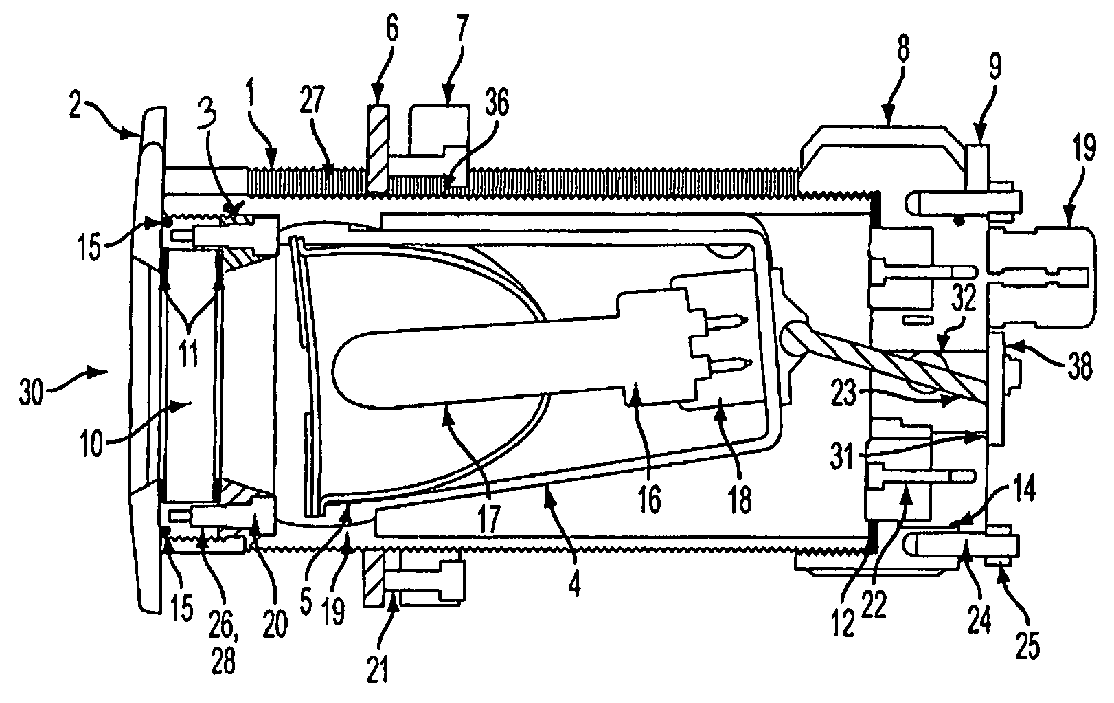
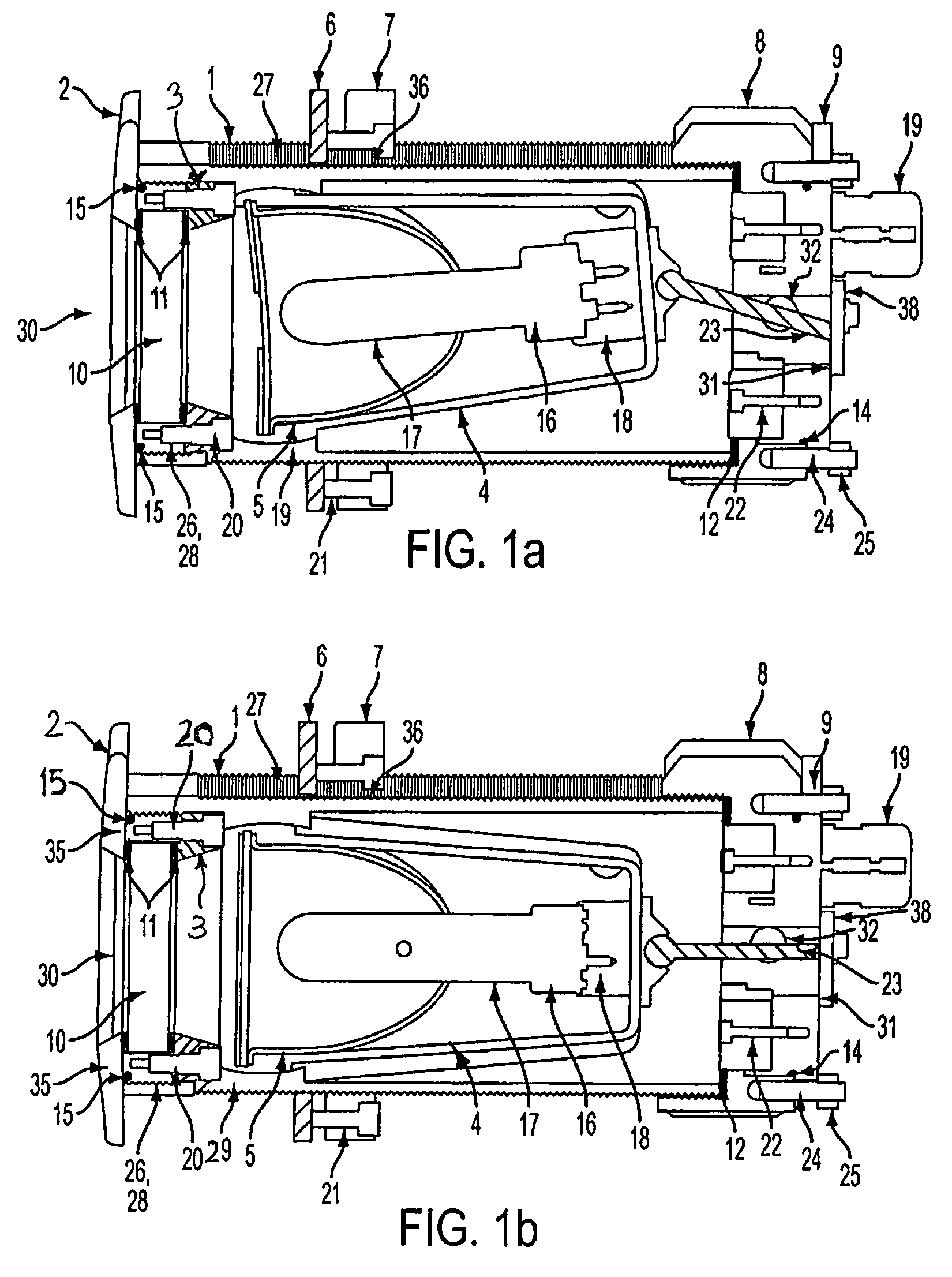
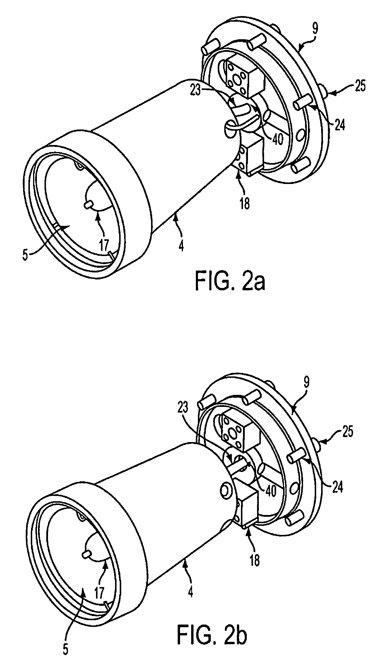
[0023]The present invention is a two-piece thru-hull view port assembly constructed to have a watertight fit in the hull or deck of a vessel. Uses for the view port assembly include, but are not limited to, a port or window for viewing using the naked eye or as a housing for one or more lights or cameras for still photography or video.

[0024]Referring to FIGS. 1a and 1b, a flange 2 having an inner and outer face is used as the exterior mounting to the vessel. A substantially transparent lens 10 having a top and a bottom surface is removably mounted on the inner surface of flange 2 and provides the window for viewing.

[0025]Lens 10 is in the shape of a disc with grounded round edges and is preferably composed of heat and pressure resistant borosilicate. As will be appreciated by one of ordinary skill in the art, any substantially transparent material that is resistant to high temperature and high pressure and is resistant to erosion and chemicals may be used. Suitable materials include...


PUM


Abstract

The present invention is a view port suitable for installation under the water line of a vessel wherein the view port comprises a flange made from a corrosion resistant material and a body made from a heat resistant material. An alternative embodiment of the invention is an underwater light in which a high intensity discharge light is installed into the above mentioned view port. The light may be swiveled while installed in the view port in order to direct the light along a desired path.

Description

[0001]This application claims priority to corresponding U.S. Provisional Application No. 60 / 783,195, filed on Mar. 16, 2006, which is related to, cross-references and incorporates by reference the subject matter of U.S. Provisional Application No. 60 / 715,625, filed on Sep. 9, 2005, and U.S. Provisional Application No. 60 / 781,678, filed on Mar. 13, 2006, the disclosures and contents of which are expressly incorporated herein by reference.BACKGROUND OF THE INVENTION[0002]Underwater view ports have been used on ships, boats or other watercraft for decorative and safety purposes as well as to aid exploration of the surrounding water. Similarly, lighting has been applied to these same watercraft to improve visibility during the dark hours or during periods of overcast or cloudy conditions. Lights have been applied so as to illuminate the sides of the watercraft in order to better visualize the watercraft from a distance, to further enhance the appearance of the watercraft, and to illumin...

Claims


Application Information

Patent Timeline
Patent Type & Authority Patents(United States)
IPC IPC(8): B63B19/00
CPCB63B45/02B63C11/49F21V21/30F21W2101/04F21V21/15F21S8/02F21W2107/20
Inventor MACDONALD, IANRASH, RANDAL
Owner UNDERWATER LIGHTS USA
Why Eureka
Try Eureka