
Fail-safe, weight-responsive skate retarder

a technology of weight-responsive and skates, applied in the direction of track brakes, railway components, transportation and packaging, etc., can solve the problems of increased speed, increased cost and danger of derailment, and increased weight of cars

Inactive Publication Date: 2007-12-11
PRECISION RAIL & MFG
View PDF31 Cites 14 Cited by
  • Summary
  • Abstract
  • Description
  • Claims
  • Application Information

AI Technical Summary

Benefits of technology

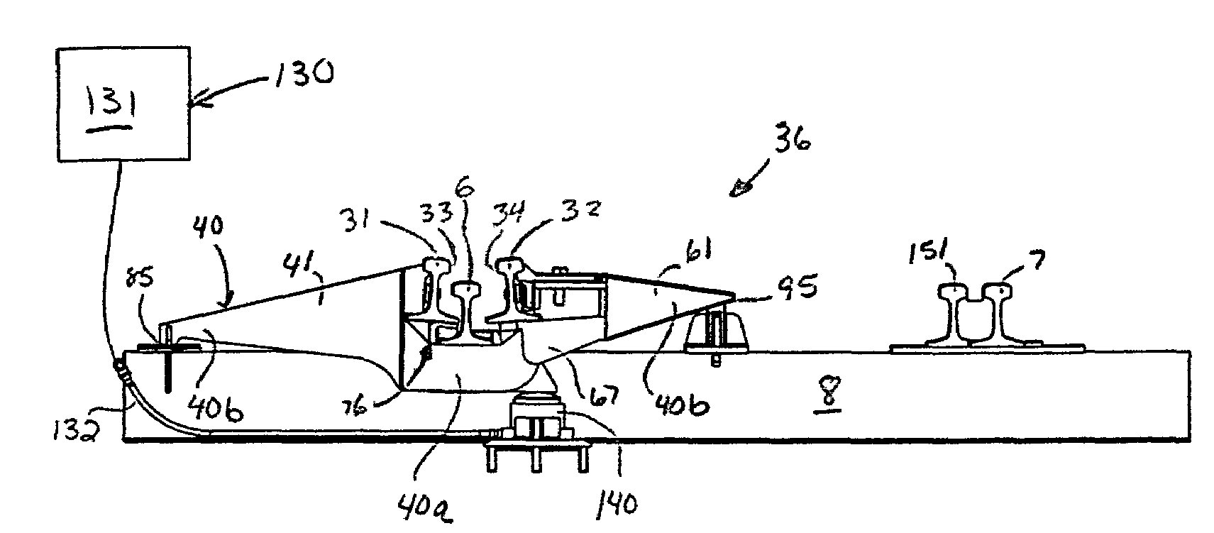
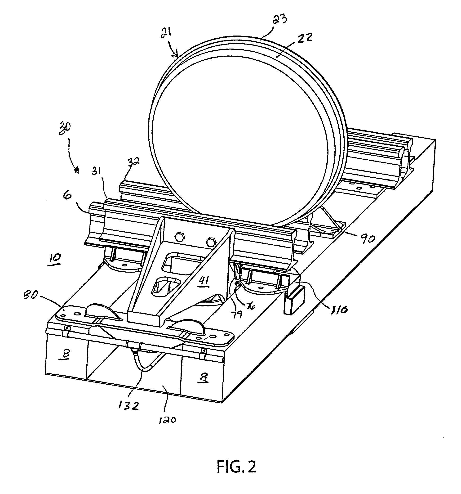
"The present invention is a fail-safe skate retarder that applies a braking force proportional to the weight of a rail car entering the retarder. The retarder includes a lever mechanism with a pair of levers rotatably joined under the running rail. Each lever holds a braking rail for engaging a wheel of the car. The retarder is normally in a lower, fail-safe position with the brake rails closer together than the width of the wheel. When the car enters the retarder, the brake rails move to a braking position, and the middle of the lever mechanism rises to lift the running rail and car. A hydraulic power unit and cylinder is activated to raise the middle of the lever mechanism to a release position where the brake rails are spread apart more than the width of the wheel. The retarder is fail-safe, meaning it does not need power to produce braking force. It is also modular, meaning it can be easily added or replaced in different yard applications. The retarder applies consistent braking force to both light and heavy cars, and it can stop both light and heavy cars in a minimal distance. It is easy to install and maintain, and it reduces installation and operating problems."

Problems solved by technology

Doing so can result in expensive and dangerous derailments.
Some cars may need to travel significantly further through the yard than others, and some cars may be significantly heavier than others.
Yet, heavier cars can pick up more speed and require more braking force to slow or stop.
This braking force is applied to the sides of the wheels and causes the car to stop.
A problem with conventional F4 weight-responsive skate retarders is that they are not fail-safe.
Weather conditions such as lightning strikes or mechanical malfunctions can cause a loss of power to the retarder and lead to dangerous situations in which the skate retarder cannot be used to stop a moving car.
Derailments or crashes can occur that result in significant damage to cars, equipment and cargo, expensive clean up and yard downtime, and serious injury or loss of life to railroad personnel.
Another problem with conventional F4 skate retarders is their “power on” time.
This increases power consumption and wear and tear on component parts such as in the hydraulic system.
A still further problem with conventional F4 skate retarders is that they are not universal.
These limitations arise due to track spacing and electrical power locations.
Right-handed and left-handed retarders are not interchangeable, which results in increased inventory and ordering problems.
A still further problem with conventional F4 weight-responsive skate retarders is the disproportionate movement of the levers and their brake rails.
Yet, the braking rail mounted to the field-side lever remains substantially stationary, which can result in the wheels of a car dragging on the field-side brake rail when in its release position.
This causes excessive wear of the field-side brake rail.
A problem with conventional (non-F4) skate retarders is that they do not apply consistent weight-responsive braking force to the car wheels.
Either too much braking power is applied to unloaded or lighter weight cars (causing the cars to derail), or too little braking power is applied to fully loaded or heavier weight cars (failing to slow or stop the car as desired).
Both situations can result in loss of life and significant property damage.
Skate retarders that are not weight responsive have difficulty applying a proper amount of force to a passing car.
Longer skate retarders tend to be more expensive and reduce the storage capacity of the yard, which reduces the overall efficiency of the yard.
A further problem with non-weight-responsive (non-F4) skate retarders is the need for regular and frequent maintenance to ensure proper spacing and shimming of the brake rails.
Because the brake force produced by the retarder is provided by springs, wear of the brake or rails results in a loss of braking power.
A still further problem with conventional skate retarders is maintenance difficulty.
Ballast gravel surrounding the retarder prevents easy access to components such as the hydraulic cylinder, and could even jam the lever arms.

Method used


Image

  • Fail-safe, weight-responsive skate retarder
  • Fail-safe, weight-responsive skate retarder
  • Fail-safe, weight-responsive skate retarder

Examples


Embodiment Construction

[0039]While this invention is susceptible of embodiment in many different forms, the drawings show and the specification describes in detail a preferred embodiment of the invention. It should be understood that the drawings and specification are to be considered an exemplification of the principles of the invention. They are not intended to limit the broad aspects of the invention to the embodiment illustrated.

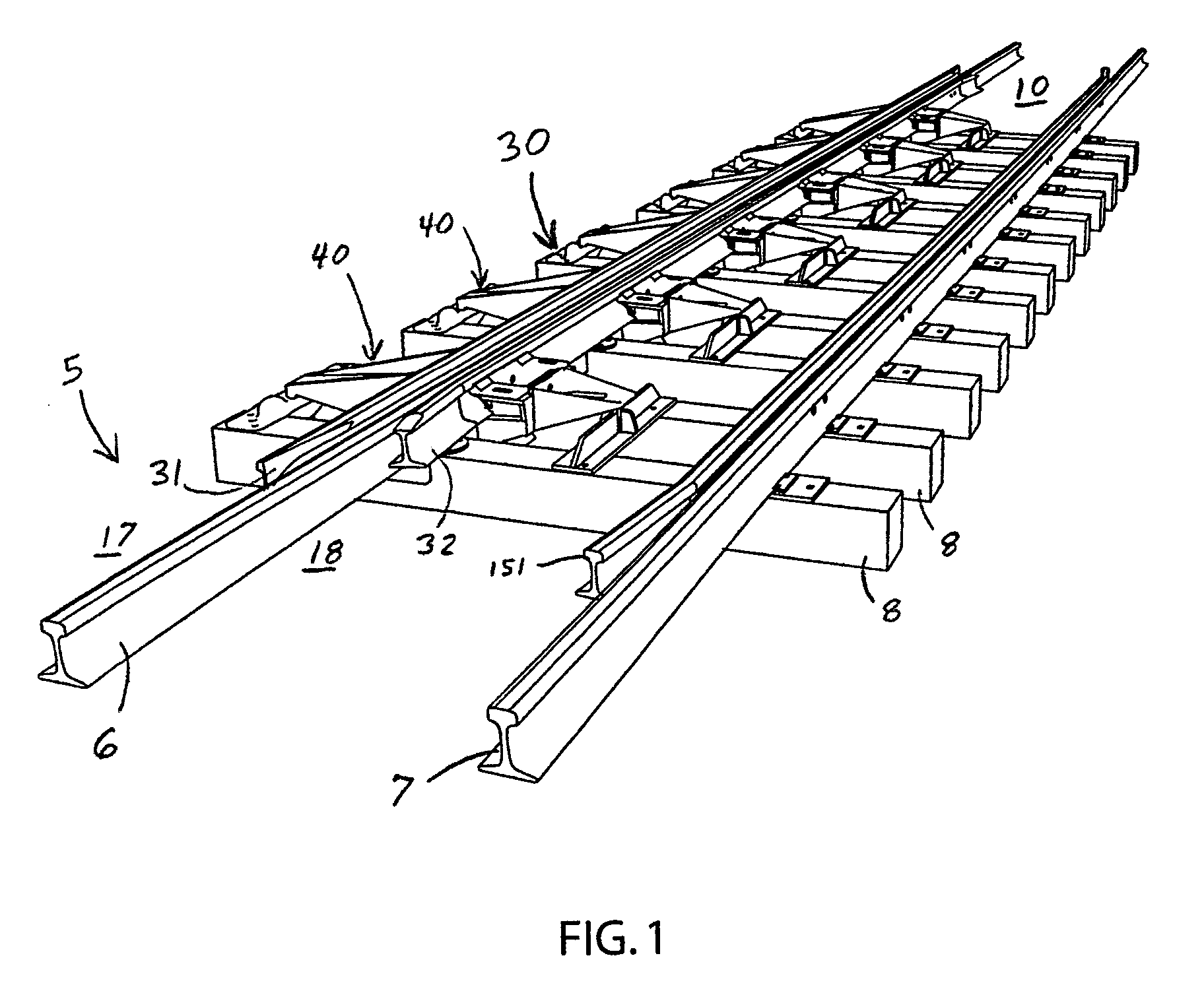
[0040]Conventional railroad tracks 5 are formed by two uniformly spaced, generally parallel steel running rails 6 and 7 mounted atop a series of wooden railroad ties 8 supported by a bed of gravel ballast. Each rail 6 and 7 has a thicker upper head 12, a thinner middle web 13, and a thicker base 14 with a flat bottom surface. The flat base 14 typically rests on the flat upper surface of the ties 8 or a flat mounting plate on the upper surface of the tie. The rails 6 and 7 are held firmly in place at their base 14 by fasteners such as spikes driven into the ties. In switching o...


PUM


Abstract

The present invention relates to a fail-safe skate retarder that applies a braking force proportional to the weight of a rail car entering the retarder. Each segment of the retarder includes a lever mechanism with a pair of levers rotatably joined under the running rail. Each lever holds a braking rail for engaging a wheel of the car. The retarder is normally in a lower, fail-safe position with the brake rails closer together than the width of the wheel. When the car enters the retarder, the wheel forces the brake rails apart into a braking position, and the middle of the lever mechanism rises to lift the running rail and car. A hydraulic power unit and cylinder is activated to raise the middle of the lever mechanism even further to a release position so that the brake rails are spread apart more than the width of the wheel.

Description

BACKGROUND OF THE INVENTION[0001]Retarders are widely used in railroad marshalling yards to control the speed of the cars as they are being directed to their desired track and location. Controlling car speed is important. Cars should not exceed specific speed limits. Doing so can result in expensive and dangerous derailments. Some cars may need to travel significantly further through the yard than others, and some cars may be significantly heavier than others. Yet, heavier cars can pick up more speed and require more braking force to slow or stop.[0002]Weight-responsive retarders such as the Type F4 skate retarder provide an amount of braking power proportional to the weight of the rail car. Skate retarders prevent cars from leaving the yard, which protects passing trains and surrounding property and persons. Each segment of the retarder includes a pair of levers joined together under the running rail and extending from opposed sides of the running rail. The levers hold a pair of br...

Claims


Application Information

Patent Timeline
Patent Type & Authority Patents(United States)
IPC IPC(8): B61K7/04
CPCB61K7/04
Inventor HEYDEN, THOMAS J.ZAWLOCKI, MARK
Owner PRECISION RAIL & MFG
Learn More