Stator cooling system for a hybrid transmission

a hybrid transmission and cooling system technology, applied in the field of cooling systems, can solve the problems of high power density motors/generators that produce a large amount of heat during operation, motor/generator requirements are very high, etc., and achieve the effect of reducing dimensional tolerance stacking, reducing necessary packaging space, and efficient cooling of stators

Active Publication Date: 2007-12-11
GM GLOBAL TECH OPERATIONS LLC
View PDF9 Cites 10 Cited by
  • Summary
  • Abstract
  • Description
  • Claims
  • Application Information

AI Technical Summary

Benefits of technology

[0012]By providing a first curved tube (and preferably a second curved tube) which circumscribes or at least partially circumscribes the stator, efficient cooling of the stator is achieved. An assembly method ensures proper alignment of components and lessens dimensional tolerance stack up between components, thereby minimizing necessary packaging space and the need to increase transmission size.

Problems solved by technology

Because limited packaging space is available within the transmission structure, the motor / generators require very high power density.
High power density motor / generators produce a large amount of heat during operation.
The stator of the motor / generator, with its high density electrical windings particularly produces a large amount of heat resulting in the need to control the temperature of the stator to ensure continuous and stable operation.

Method used


Image

  • Stator cooling system for a hybrid transmission
  • Stator cooling system for a hybrid transmission
  • Stator cooling system for a hybrid transmission

Examples


first embodiment

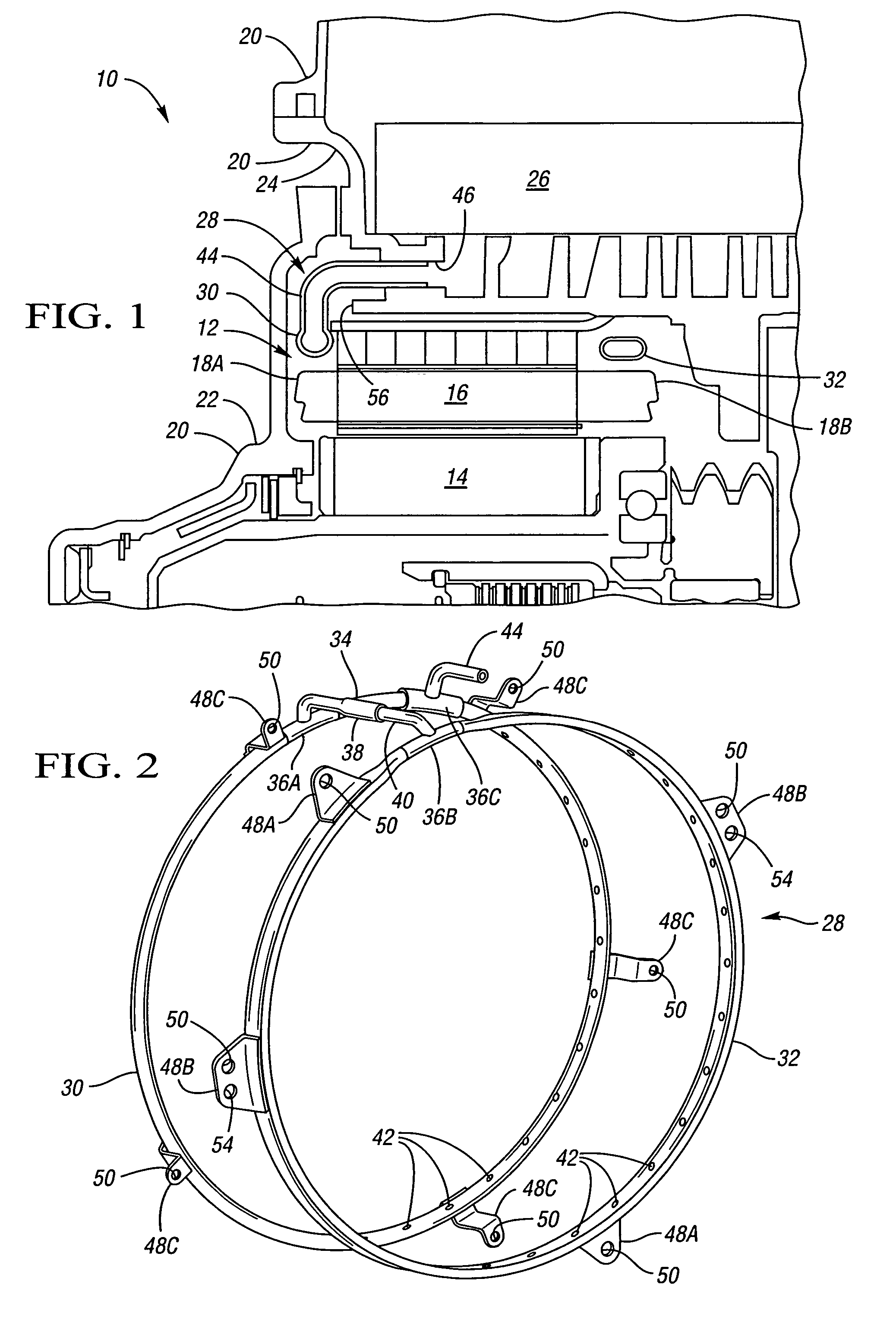
[0022]a cooling system 28 for cooling the annular stator 16 and particularly the stator windings 18A, 18B is illustrated in FIGS. 1 and 2. The transmission 10 may include a second motor / generator, in which case a second cooling system 28 may be used to cool the stator of the second motor / generator. Referring to FIG. 2, a first curved tube 30 and a second curved tube 32 are connected via a connector tube 34 that interfaces with the tubes 30, 32 with T-joints 36A, 36B. The connector tube 34 has a first portion 38 extending from T-joint 36A which interfits with a second portion 40 that extends from the T-joint 36B to establish fluid connection between the first and second tubes 30, 32. Openings (not shown) in the tubes 30, 32 interface with the respective connector tube portions 38, 40 to allow fluid flow from the first tube 30 through the connector tube 34 to the second tube 32. Each of the tubes 30, 32 is formed with or is machined with a plurality of circumferentially spaced fluid o...

second embodiment

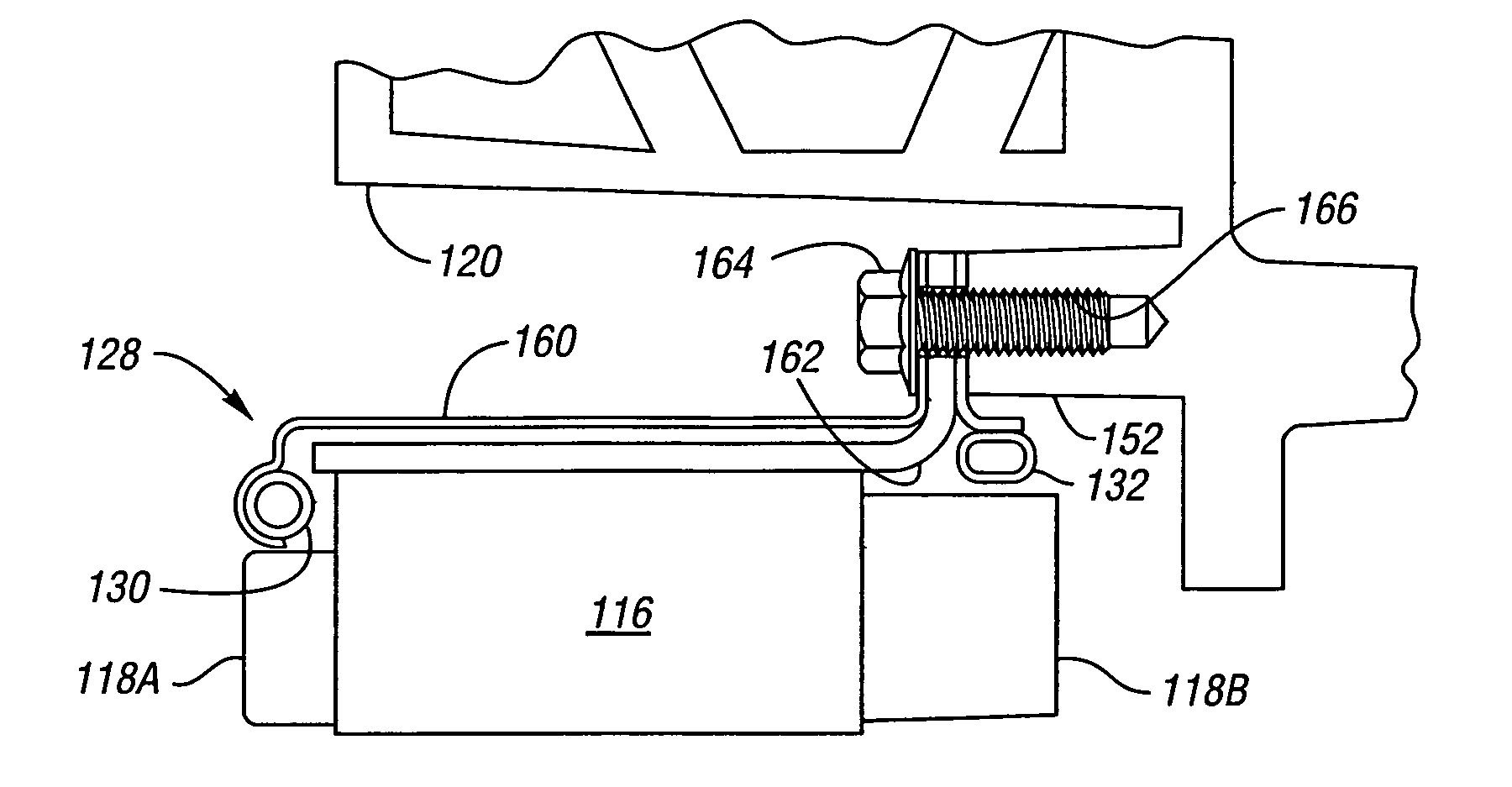
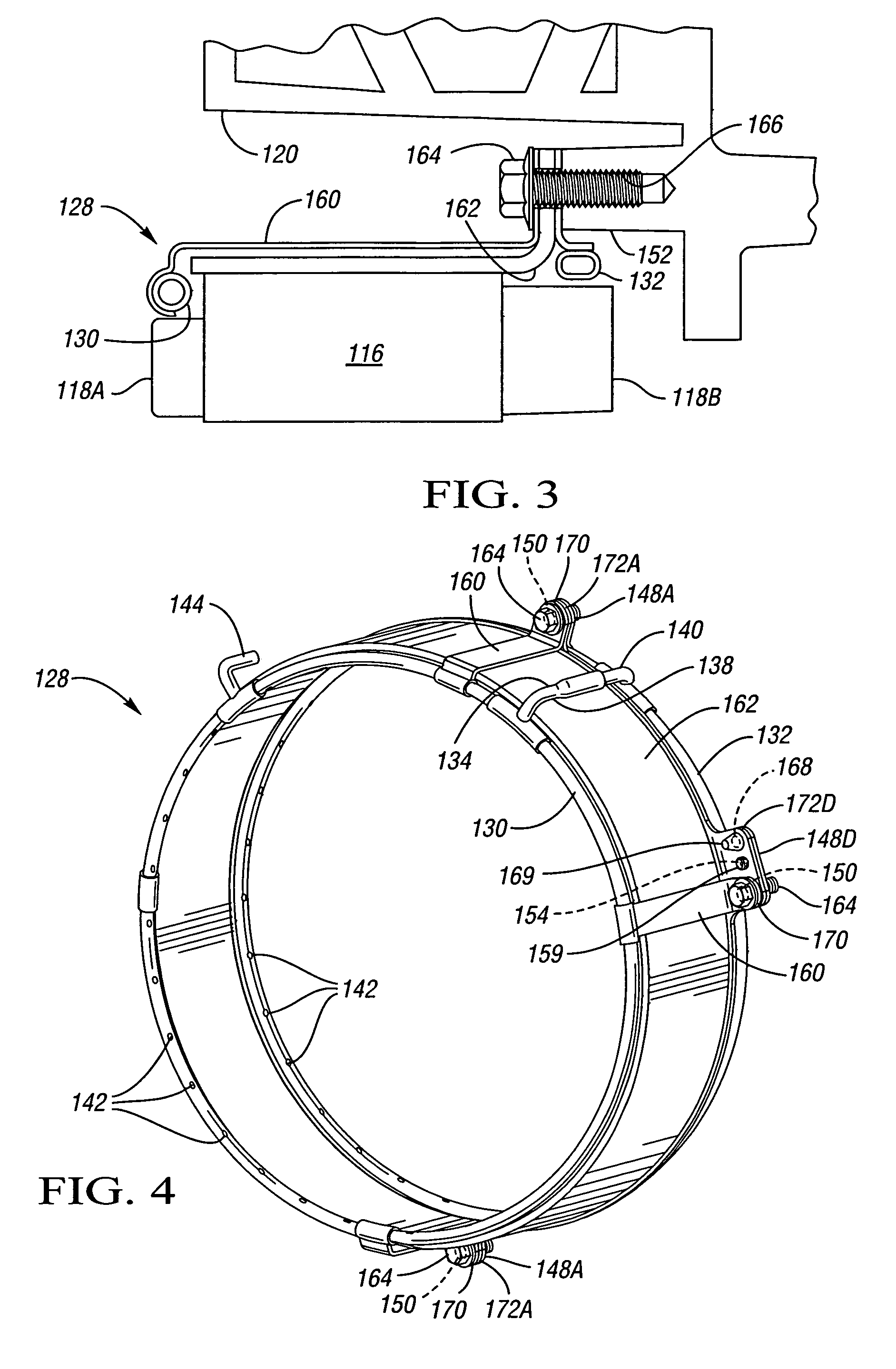
[0026]Referring to FIGS. 3-5, a cooling system 128 is illustrated. The cooling system 128 includes first and second tubes 130, 132 and elongated brace 160 and a stator housing 162 as will be described below with respect to FIGS. 3-5. As best shown in FIG. 3, the cooling system 128 is supported at a single plane of bosses 152 of the transmission casing 120.

[0027]Referring to FIG. 4, the cooling system 128 includes first and second tubes 130 and 132, respectively, with an intake conduit 144 extending from tube 130 and in fluid communication therewith to receive fluid from a valve body in the transmission casing 120 similarly to intake conduit 44 of FIG. 1 (the intake conduit 144 is not shown at the cross sectional location of FIG. 3). As with the first embodiment, a connector tube 134 includes a first portion 138 extending from the first tube 130 that is interference or sealingly fit with a second portion 140 extending from the second tube 132 to establish fluid communication between ...


PUM


Abstract

A cooling system for an annular stator housed within a transmission casing includes a first curved tube sufficiently sized to at least partially circumscribe the stator when the tube is placed within the casing. The first tube has a plurality of circumferentially spaced fluid openings. An intake conduit connects the first tube to the transmission casing to deliver fluid through the tube for flow through the fluid openings to cool the stator. Preferably, a second like curved tube is also provided and a connector tube connects the first and second tubes to allow fluid flow therebetween. A method of assembling a cooling system is also provided.

Description

TECHNICAL FIELD[0001]This invention relates to a cooling system for a stator of a motor / generator in a hybrid electro-mechanical transmission and a method of assembling such a cooling system.BACKGROUND OF THE INVENTION[0002]A hybrid electro-mechanical vehicular transmission utilizes interactive differential gear arrangements that are operatively connected to an engine and typically two motor / generators. Selective utilization of torque transfer devices enables power transfer via the differential gear arrangements from the engine and / or motor / generators to the output member of the transmission.[0003]A power transmission in an electro-mechanical transmission is described in commonly owned U.S. Provisional Application No. 60 / 590,427 entitled Electrically Variable Transmission with Selective Fixed Ratio Operation, filed Jul. 22, 2004, and hereby incorporated by reference in its entirety.[0004]Hybrid system motor / generators, especially those for strong hybrid systems, must be high powered...

Claims


Application Information

Patent Timeline
Patent Type & Authority Patents(United States)
IPC IPC(8): H02K9/00
CPCB60K6/26H02K5/20H02K7/006B60L1/02B60L3/0061B60L11/14H02K9/19B60K2001/003B60L2220/50B60L2240/36B60L50/16Y02T10/64Y02T10/7072H02K5/203Y02T10/70
Inventor PASHNIK, RICHARD A.SOWUL, HENRYK
Owner GM GLOBAL TECH OPERATIONS LLC
Why Eureka
Try Eureka