
Transmission method with fading distortion or frequency offset compensation

Inactive Publication Date: 2007-12-11
NAT INST OF INFORMATION & COMM TECH
View PDF7 Cites 3 Cited by
  • Summary
  • Abstract
  • Description
  • Claims
  • Application Information

AI Technical Summary

Benefits of technology

[0020]In addition, the eleventh aspect of the present invention comprises any of said first through fifth aspects, but in order to reduce the amount of computation required while preserving high estimation accuracy, it further comprises the steps of: varying the proportion of the number of frames on which compensation is performed depending on the value of the fading component found from said spectrum.

Problems solved by technology

However, with this method, each type of compensation is performed with a different type of known symbol, thus complicating the structure of the transceivers and reducing the fraction occupied by the data portion so there is a problem in that the transmission rate is reduced,
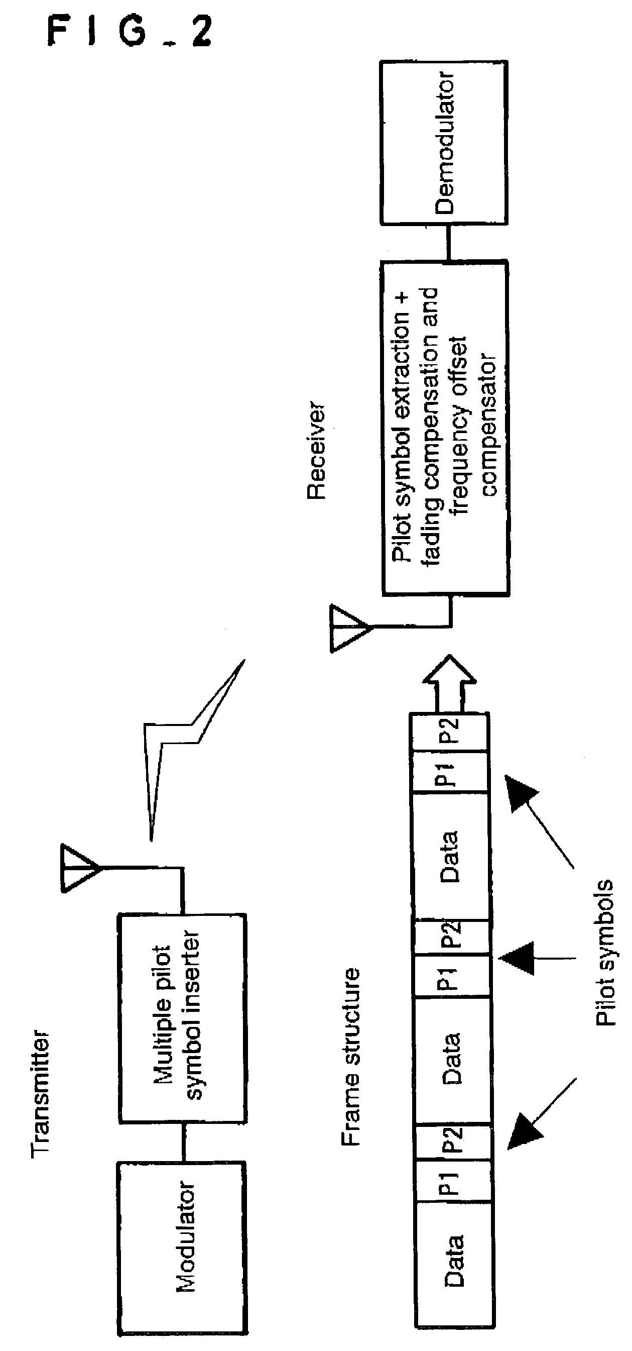
However, with this method, phase differences between the adjacent P1 and P2 arising from the phase noise suffered by P1 and P2 occur, so the frequency offset may differ greatly from the estimated value of the frequency offset.
Moreover, if three or more adjacent pilot symbols are used in order to reduce these phase errors, there is a problem in that the fraction occupied by the data portion is relatively reduced and the transmission rate is lowered.
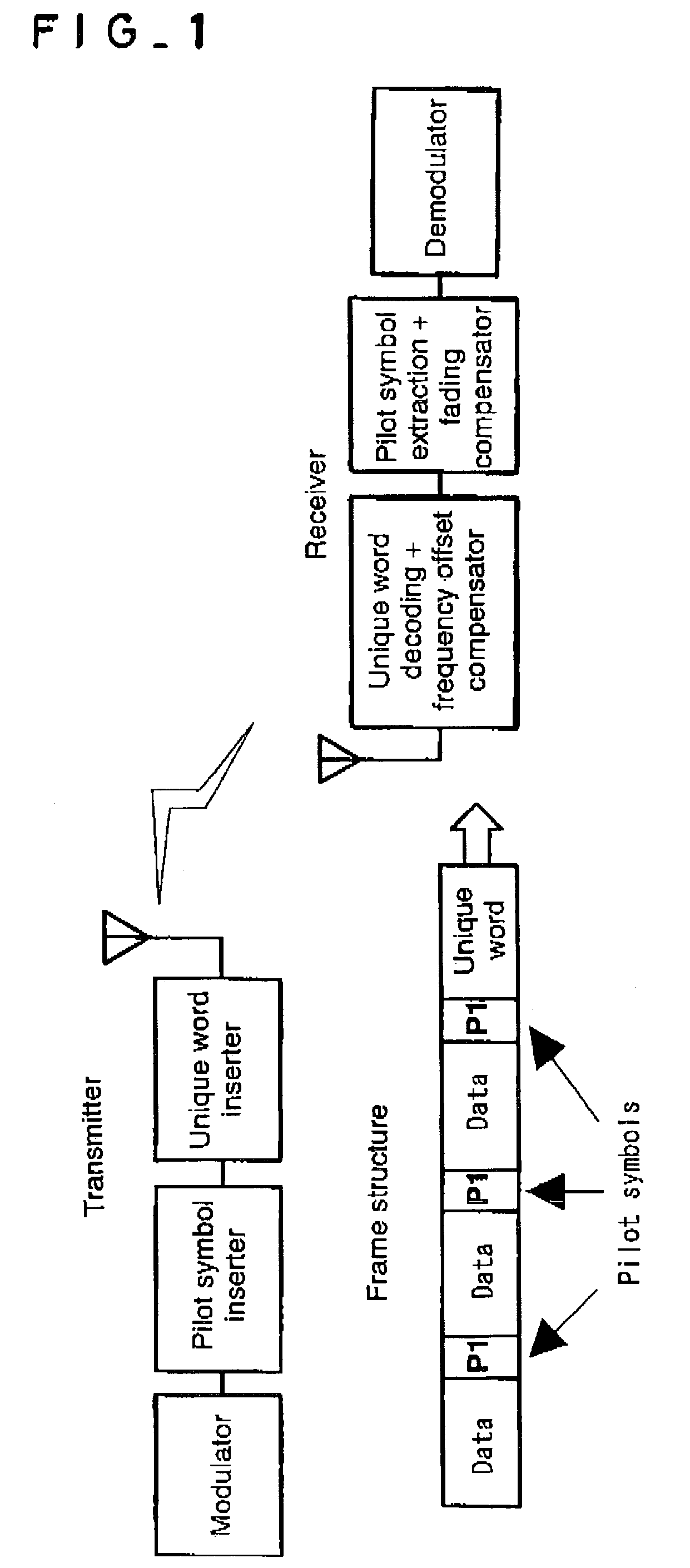
As described above, with the first related art that uses unique words, there are problems in that the structure of the transceiver becomes complex and the fraction occupied by the data portion is reduced so that the transmission rate is lowered, and with the second related art that uses two consecutive pilot symbols, there are problems in that the frequency offset may be much different from the estimated value and if three or more adjacent pilot symbols are used, the fraction occupied by the data portion is relatively reduced, also lowering the transmission rate.

Method used


Image

  • Transmission method with fading distortion or frequency offset compensation
  • Transmission method with fading distortion or frequency offset compensation
  • Transmission method with fading distortion or frequency offset compensation

Examples


embodiment 1

Preferred Embodiment 1

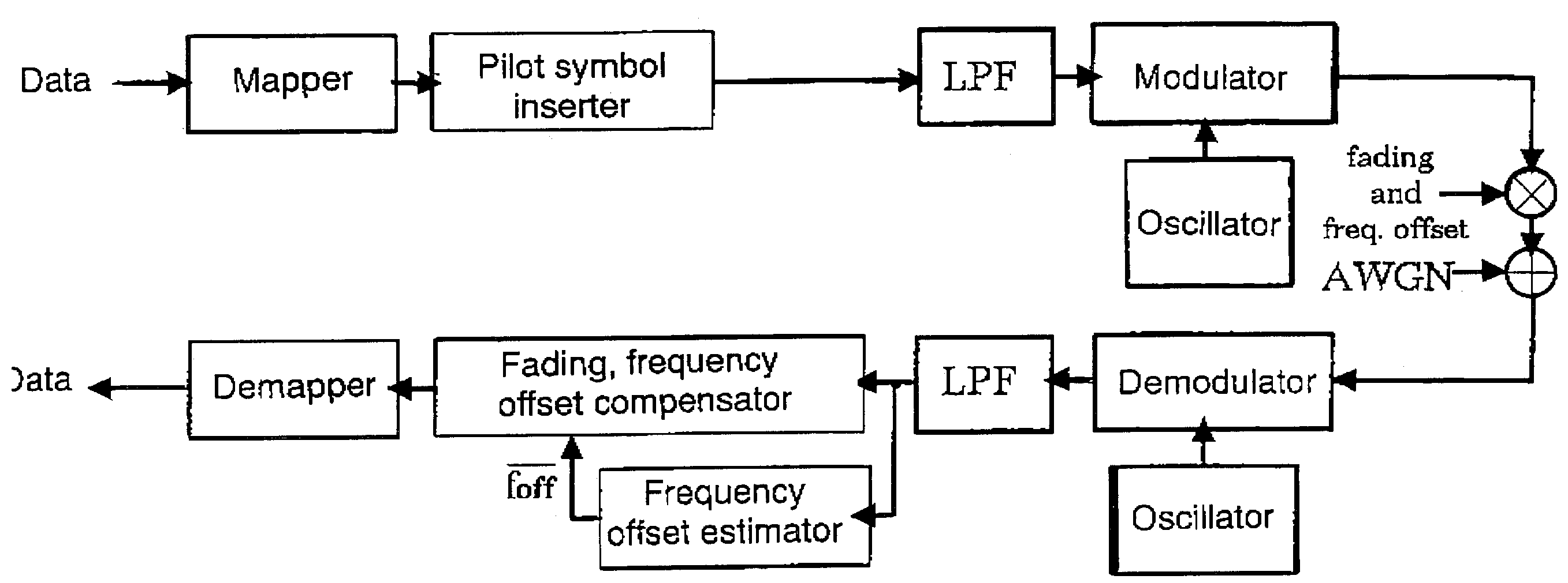
[0076]In order to demonstrate the effects of the present invention, as Preferred Embodiment 1, computer simulations of the transmission systems shown in FIGS. 4 and 8 were performed and the response was measured. Table 1 shows the simulation parameters. The modulation method was uncoded and Gray-mapped 16QAM, and the transmission rate (=1 / TS) was 1.6 Mbps. In the following, it was assumed that there was perfect clock and frame synchronization. In the bit-error-rate (BER) calculation, to avoid the degradation caused by the initial ƒoff(k) error in equation (10), the calculation was started at 48 frames.

[0077]

TABLE 1Simulation parametersModulationUncoded 16QAMMappingGrayFadingFlat RayleighLow-pass filterSquare root raised cosine ρ = 0.5Gaussian filterBTs = 4.0Transmission rate1.6 Msymbols / sN16Np16Cs 4Kf16

[0078]In Preferred Embodiment 1, the performance was calculated under the fixed frequency-offset conditions, that is, ƒoff(t)=const. FIGS. 12 and 13 show the BER...

embodiment 2

Preferred

[0081]Next, the performance of this method in an environment in which ƒoff changes was calculated by the following equations:

ƒoff(k)=ƒ0+αk [linear]  (24)

[0082]foff⁡(k)=f0+αTs⁢sin⁡(wTs⁢k)⁡[sinusoidal](25)

The frequency offset changes when the station changes its direction, velocity or acceleration. The above equations simulate the simplest examples of these, where equation (24) is an example in which the frequency offset changes linearly and equation (25) is an example in which it changes sinusoidally. Regarding the acceleration of ƒoff (ƒoff″), while the former is 0 the latter is not 0. Note that in the following, it is assumed that α=2.0 in equation (24) and α=0.2 and w=10 in equation (25), and the BER was calculated within the range of |ƒoff(k) / ƒS|≦0.05 to avoid the degradation caused by the LPF and to evaluate the pure following performance of the method only for the frequency offset changes.

[0083]FIGS. 16 and 17 show the BER versus the Eb / N0. As is evident from the figur...


PUM


Abstract

A transmission method with compensation for fading distortion or frequency offset distortion in digital communications using pilot signals, comprises the steps of: receiving modulated radiofrequency signals, demodulating the digital signals carried by said radiofrequency signals, extracting pilot signals from the received radiofrequency signals or demodulated digital signals, finding a spectrum of the extracted pilot signals, finding fading components or frequency-offset components from said spectrum, and using one of these components to compensate the received radiofrequency signal or estimate the original digital signal from the demodulated digital signals.

Description

BACKGROUND OF THE INVENTION[0001]1. Field of the Invention[0002]The present invention relates to a means of simultaneously compensating for propagation path distortion and frequency offsets suffered by a moving station or the like in digital wireless communication, and to a method of compensating for fading or frequency offsets in a propagation environment wherein one or the other occurs in digital wireless communication, and particularly to transmission method with compensation for fading distortion and frequency offset compensation and used as a propagation path distortion-compensation technique using pilot signals in mobile wireless communication.[0003]2. Description of the Prior Art[0004]In digital wireless communication using moving stations, fading caused by various changes in the environment and frequency offsets arising due to the movement of the station are known to occur. FIG. 1 shows the frame structure in a first related art used to compensate for the fading and frequenc...

Claims


Application Information

Patent Timeline
IPC IPC(8): H03D1/04H04B7/26H04L25/02H04B7/005H04L25/03H04L27/00
CPCH04L25/0228H04L2025/03522H04L2027/0093H04L2027/0053H04L2027/0065H04L2027/003
Inventor OKAMOTO, EIJI
Owner NAT INST OF INFORMATION & COMM TECH
Learn More