
Voice communications method, voice communications system and recording medium therefor

Inactive Publication Date: 2007-12-11
NIPPON TELEGRAPH & TELEPHONE CORP
View PDF10 Cites 21 Cited by
  • Summary
  • Abstract
  • Description
  • Claims
  • Application Information

AI Technical Summary

Benefits of technology

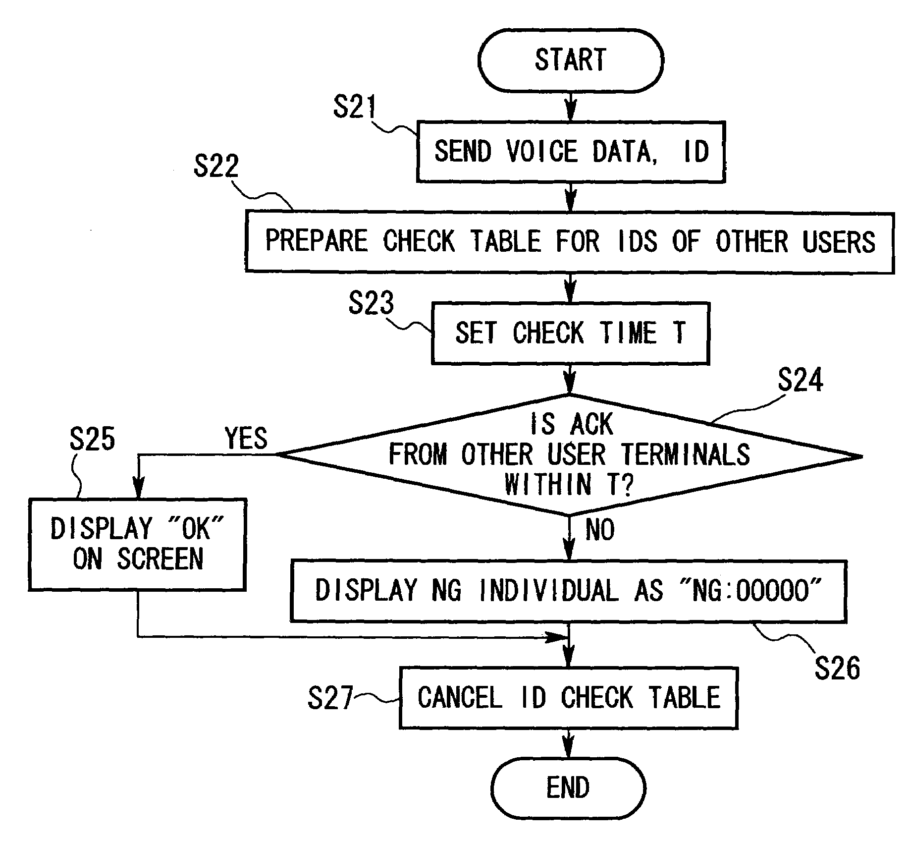
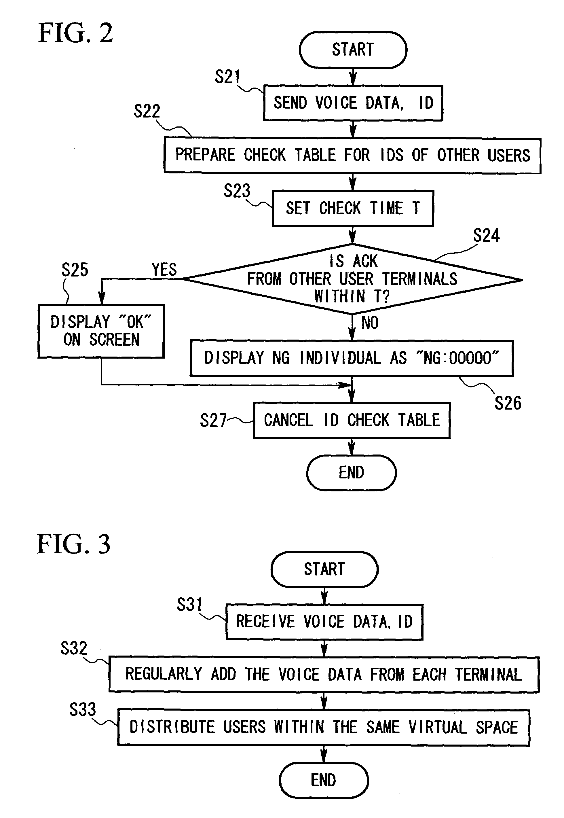
[0010]It is therefore the objective of the present invention to provide a voice communications method, a voice communications system, and a recording medium for recording the programs therefor, that enables a talker to visually confirm that his voice has reached his listener.
[0011]It is also the objective of the present invention to provide a voice communications method, a voice communications system, and a recording medium for recording the programs therefor, with which conversational timing can be easily achieved.
[0012]It is a further objective of the present invention to provide a voice communications method, a voice communications system, and a recording medium for recording the programs therefore, which enables voice data from the talker terminal to be delivered to a specific listener terminal only, without having to form a private group between the talker terminal and the listener terminal.

Problems solved by technology

Although conventional voice communications methods enable the talker to be identified, it has not been possible for the talker to know whether or not his voice has reached the listener.
However, since voice data is comparatively large data, the arrival of voice data from the talker terminal at the listener terminal is slightly delayed.
In addition, a slight delay in the arrival of voice data may arise due to variation in traffic and buffering in the above-described network system.
This also results in a delay.
Since the arrival of the data is slightly delayed in this way, good conversational timing has been difficult to achieve in conventional voice communications methods due to such problems as voice data from the other parties arriving just as the user begins to speak, or arriving immediately after the user has spoken, etc.
For this reason, users must converse while anticipating this delay, making this arrangement quite inconvenient and burdensome to the user.

Method used


Image

  • Voice communications method, voice communications system and recording medium therefor
  • Voice communications method, voice communications system and recording medium therefor
  • Voice communications method, voice communications system and recording medium therefor

Examples


first embodiment

1. First Embodiment

[0040]The first embodiment of the present invention will now be explained in detail with reference to the accompanying figures.

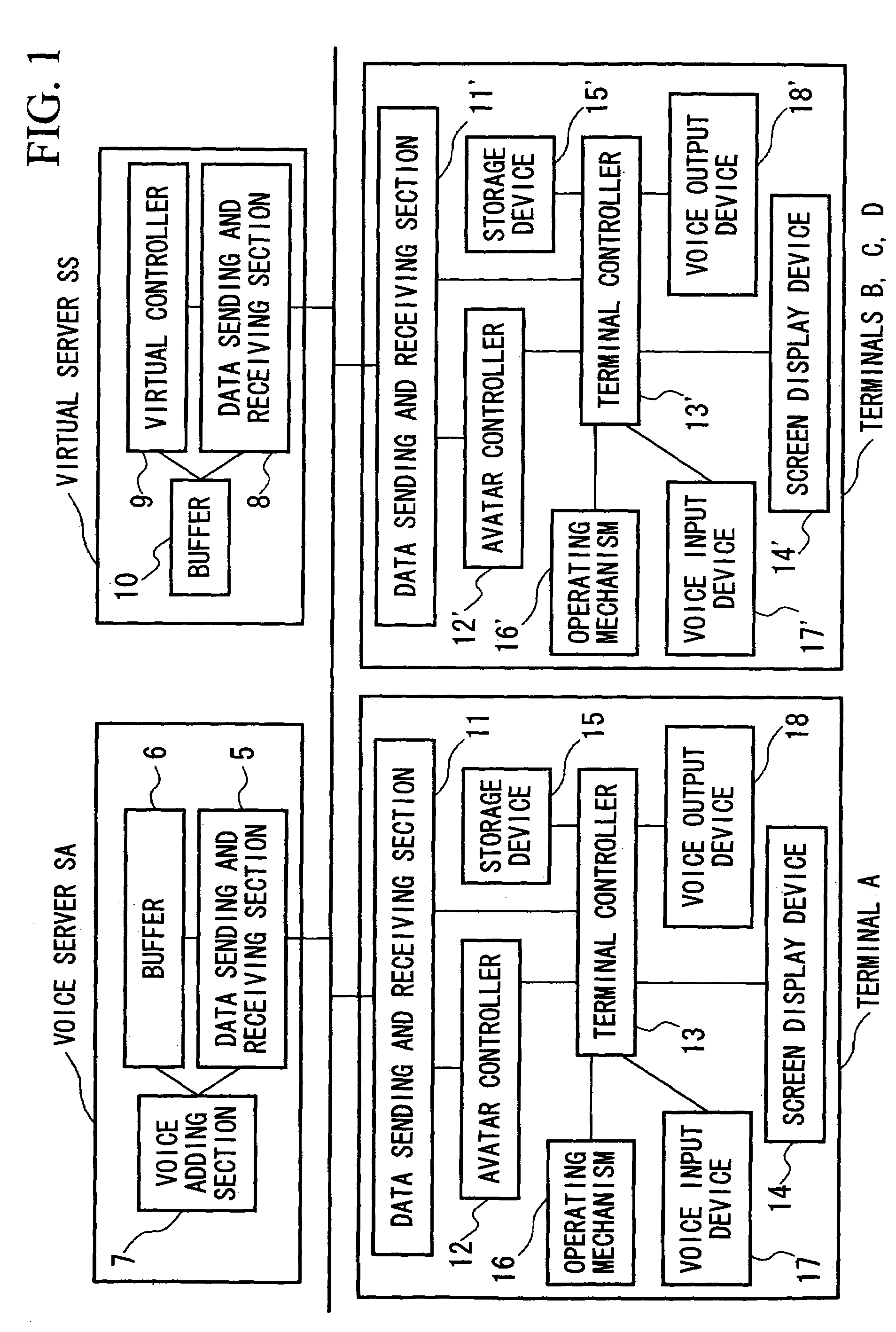
[0041]FIG. 1 is a block diagram showing an example of the design of a network system according to this embodiment. This network system is composed of multiple terminals A to D, virtual server SS, and voice server SA. Note that the number of terminals in the network system is not limited to 4. Terminals A to D, virtual server SS, and voice server SA are connected together by communications circuits. Any type of communications circuit is acceptable, including a WAN (Wide Area Network), LAN (Local Area Network), or the Internet. Terminals A to D, virtual server SS, and voice server SA send and receive information in message form each other.

[0042]Terminals A to D, virtual server SS and voice server SA are formed of a computer device consisting of a CPU (central processing unit) and its peripheral circuits. This computer device functions as sho...

second embodiment

2. Second Embodiment

[0064]A second embodiment of the present invention will now be explained in detail with reference to the accompanying figures.

[0065]The block diagram of the network system according to this embodiment is identical to the block diagram of the network system according to the first embodiment (see FIG. 1). However, the processing described in each block is different between the first and second embodiments. Accordingly, the processing according to this embodiment will now be explained. Of the processing performed in this embodiment however, the terminal log-in processing and the avatar update processing are identical to the processing explained under sections “(1) Terminal log-in” and “(2) Avatar update” for the first embodiment above. An explanation of these will therefore be omitted. The processing for sending and receiving voice data according to this embodiment will be explained below using as an example the case in which terminal A sends voice data to terminals...

third embodiment

3. Third Embodiment

[0074]A third embodiment of the present invention will now be explained in detail with reference to the accompanying figures.


PUM


Abstract

The objective of the present invention is to enable a speaker to visually confirm whether or not his voice has reached a listener. In order to achieve this objective, in the present invention, the listener terminal generates a reception result for voice data, and the talker terminal displays the reception state based on this reception result.It is a further objective of the present invention to enable conversational timing to be achieved easily. In order to achieve this objective, in the present invention, the talker terminal sends utterance data prior to sending voice data, this utterance data being shorter than the voice data. The listener terminal displays the talker terminal's utterance based on this utterance data.Another objective of the present invention is to deliver voice data from the talker terminal to a particular listener terminal only, without having to form a private group. In order to achieve this objective, in the present invention, the server stores permission or denial for sending data from an optional terminal to another optional terminal, and distributes the voice data based on this storage.

Description

BACKGROUND OF THE INVENTION[0001]1. Field of the Invention[0002]The present invention is related to a voice communications method, a voice communications system, and a recording medium for recording the programs therefore, that are used in a network system in which there are a plurality of connected terminals for carrying out conversation between the users of these terminals.[0003]This specification is based on patent applications previously filed in Japan (Japanese Patent Application Hei 11-192012, Japanese Patent Application Hei 11-204533, and Japanese Patent Application 2000-118599), these applications being incorporated within this specification as a portion thereof.[0004]2. Description of the Related Art[0005]In a network system having a plurality of connected terminals, the server provides a number of virtual spaces that can be accessed through these terminals. When multiple terminals access the same virtual space, the users of these terminals are displayed by a specific displ...

Claims


Application Information

Patent Timeline
IPC IPC(8): H04M1/64
CPCH04M1/6033H04M3/567H04M2203/1025
Inventor MORIUCHI, MACHIOKIYOSUE, YASUYUKIKONAGAI, SYUNSUKEMASAKI, SHIGEKI
Owner NIPPON TELEGRAPH & TELEPHONE CORP
Learn More