
Horizontal curve sawing apparatus

a sawing apparatus and horizontal curve technology, which is applied in the direction of metal sawing devices, band saws, manufacturing tools, etc., can solve the problems of compound less accurate alignment of the cant relative to the blades and the curvature of the cant, and the end portion of the cut board often will not have the correct thickness and will have to be scrapped. , to achieve the effect of smooth and accurate cutting

Inactive Publication Date: 2007-12-18
BREWER SR CLARENCE R
View PDF21 Cites 18 Cited by
  • Summary
  • Abstract
  • Description
  • Claims
  • Application Information

AI Technical Summary

Benefits of technology

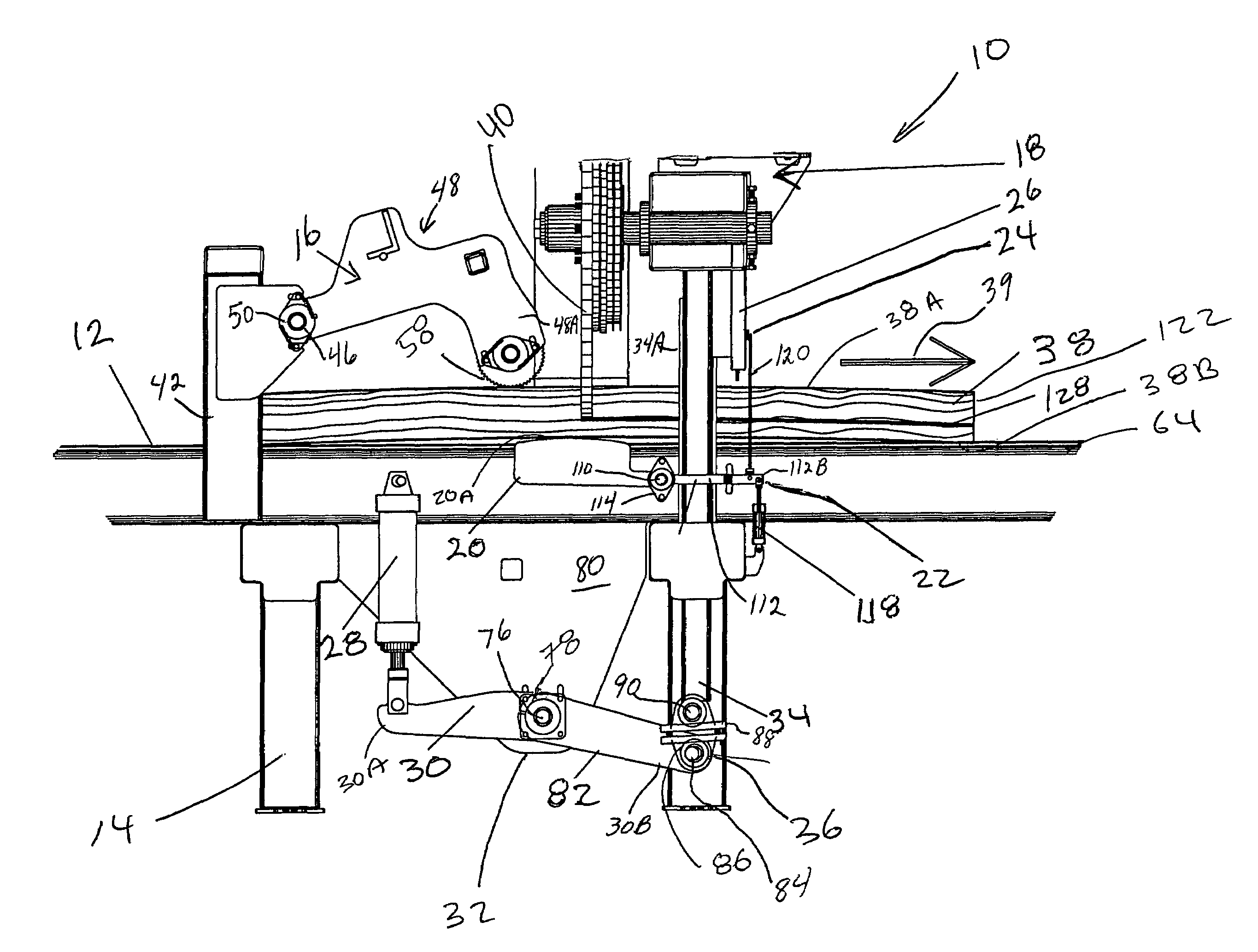
[0011]It should be noted that the displacement sensor (i.e. the shoe) is located directly below (or above) the saw blade for greatest accuracy. For a mechanical sensor, such as a shoe, it may be easier to track the displacement of the cant on the bottom surface, because there is no interference from the saw. However, if the sensor does not have to physically touch the cant, such as when the sensor is an optical or laser scanner, this measurement may just as readily be taken at the top surface of the cant, directly above the saw blade.
[0013]As soon as the cant reaches the saw blade, the sensor can immediately begin sensing the position of the bottom surface of the cant, and the programmable logic controller can begin making corresponding corrections to the position of the saw head in order to follow the contour of the cant from the first end to the last end. There is no loss of control at any point throughout the entire length of the cut.
[0014]The smooth (sawn) side of the cant is placed on the conveyor, but this side can be either convex or concave, or it can, in fact, have a compound curvature, including both concave and convex portions at different points along its length. The saw can accommodate any of these conditions without requiring any further alignment of the cant relative to the displacement sensor. The sensing by the displacement sensor is done on the smooth side of the cant, not on the wany side, resulting in a smooth, accurate cut.

Problems solved by technology

This means that the end portion of the cut board frequently will not have the correct thickness and will have to be scrapped.
Furthermore, the cant is moved laterally by the orienting pressure roller 6 which is also acting against the wany side of the cant, which results in a less accurate alignment of the cant relative to the saw blades and the relative to the curvature of the cant.
This also means that a cant with a compound curvature (one which is concave in a portion of its length and convex in another portion of its length) cannot be adequately handled by the saw taught in Kenyon.

Method used


Image

  • Horizontal curve sawing apparatus
  • Horizontal curve sawing apparatus
  • Horizontal curve sawing apparatus

Examples


Embodiment Construction

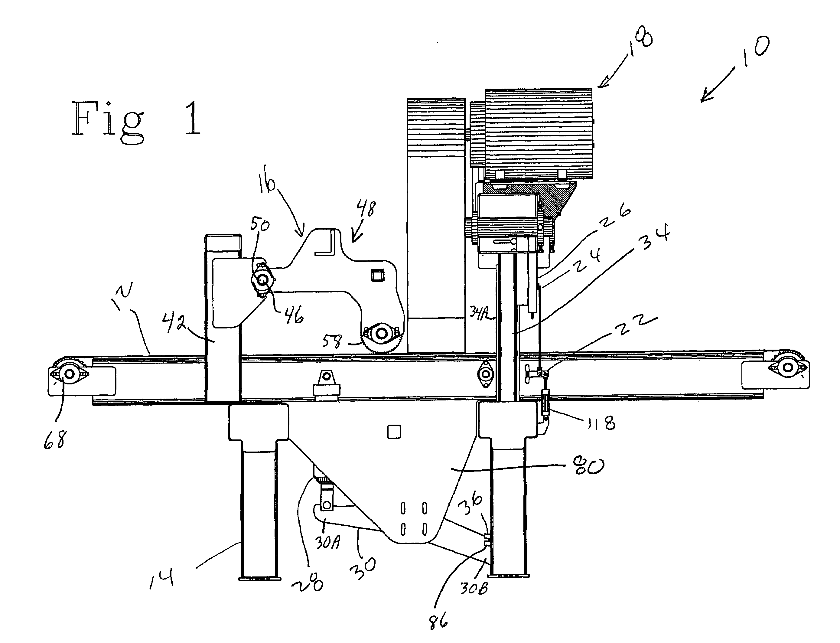
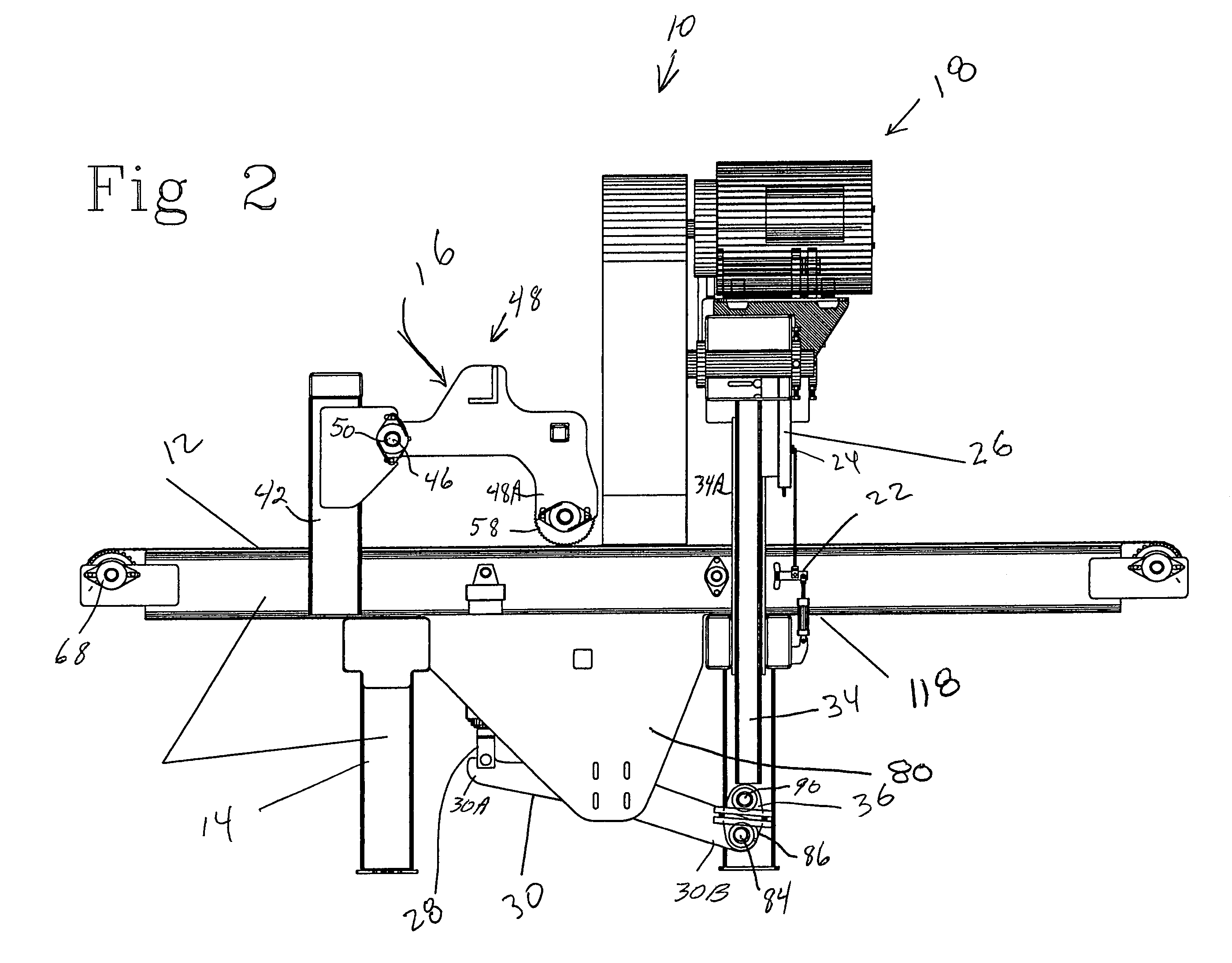
[0026]FIGS. 1 through 8 show a cant saw 10 made in accordance with the present invention. Referring briefly to FIG. 8, the cant saw 10 includes a conveyor table 12 with a frame including legs 14, a hold down and feeder assembly 16, a horizontally cutting saw head 18, and a cant curvature sensing shoe 20. A linkage mechanism 22 connects the sensing shoe 20 to a sliding magnetic pick-up mechanism 24, which slides inside a probe 26 that is fixed relative to the saw head 18. A programmable logic controller 24 (shown in FIG. 9) receives a signal from the probe 26 and, in turn, sends a signal to a piston actuator 28 to extend or retract in order to raise or lower the saw head 18 via an actuator arm 30 which pivots about a fulcrum 32. The actuator arm 30 is connected at one end 30A to the piston actuator 28, and it is connected at the other end 30B to a first pivot shaft 84, which is connected to a saw head lift shaft 90 through a double knuckle arrangement 36. The saw head lift shaft 90 i...


PUM

PropertyMeasurementUnit
displacementaaaaaaaaaa
thicknessaaaaaaaaaa
movementaaaaaaaaaa

Abstract

A saw for cutting a cant by sensing the curvature of the cant and raising or lowering the saw blade in order to follow the curvature when cutting the cant.

Description

[0001]This application is a continuation-in-part of U.S. Utility application Ser. No. 10 / 317,896, filed Dec. 12, 2002 now abandoned, which claims priority from U.S. Provisional Application Ser. No. 60 / 360,591, filed Feb. 28, 2002, both of which are hereby incorporated herein by reference.BACKGROUND OF THE INVENTION[0002]The present invention relates to a sawing apparatus for cutting a cant along a curve. More particularly, it relates to a sawing apparatus which senses the curvature of a cant along a smooth (or sawn) side of the cant and adjusts the saw head by raising or lowering the saw head so as to cut a board of a preset thickness, following the curvature of the cant.[0003]In prior art cant cutting saws, such as that described in Kenyon (U.S. Pat. No. 4,127,044), the vertically oriented saw head remains stationary (is not moved up or down or sideways) while the cant is displaced horizontally so that the cant may be cut following the curvature of the cant. A sensing roller 25 (al...

Claims


Application Information

Patent Timeline
Patent Type & Authority Patents(United States)
IPC IPC(8): B27M1/08
CPCB27B15/02Y10T83/543Y10T83/538Y10T83/7101
Inventor BREWER, SR., CLARENCE R.
Owner BREWER SR CLARENCE R
Learn More