Sound suppressor

Active Publication Date: 2007-12-18
SMITH & WESSON
View PDF21 Cites 117 Cited by
  • Summary
  • Abstract
  • Description
  • Claims
  • Application Information

AI Technical Summary

Benefits of technology

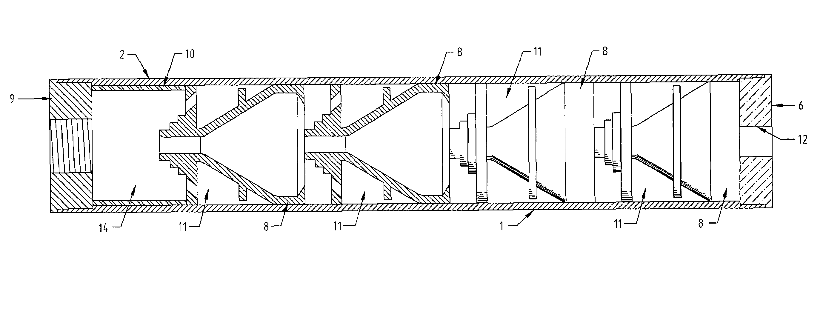
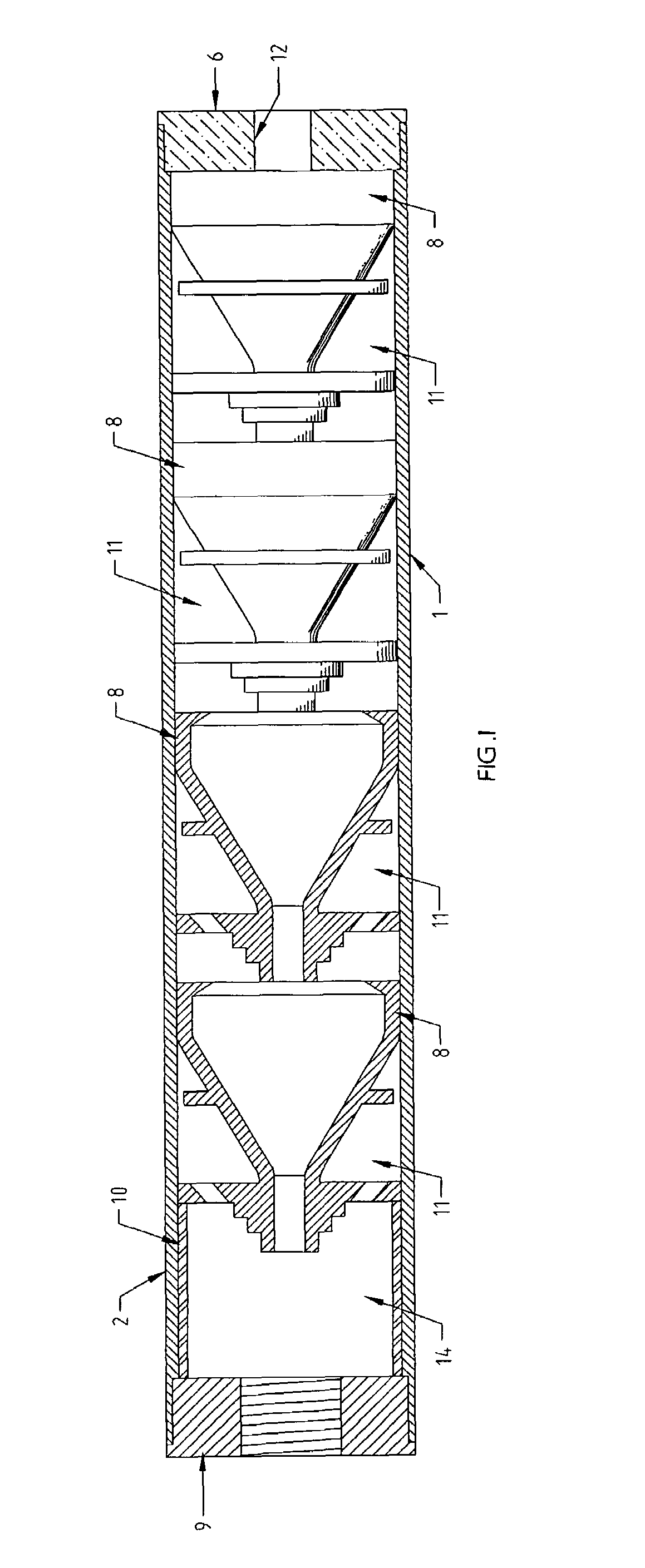
[0009]The present invention is a sound suppressor for a firearm for reducing sound and flash levels upon the discharge of a firearm. The sound suppressor comprises a cylindrical housing, a proximal end cap with means for attachment to a firearm and to the cylindrical housing, a distal end cap with means for attachment to the housing, and a plurality of baffles positioned within the housing and between the proximal end and distal end caps of the suppressor. Separate cylindrical spacer e

Problems solved by technology

Quite complex baffle structures are known in the prior art.
However, while such a modified ‘K’ baffle worked well with pistol caliber firearms, the asymmetry caused some detrimental effect on accuracy when used with rifle ca

Method used


Image

  • Sound suppressor
  • Sound suppressor
  • Sound suppressor

Examples


Embodiment Construction

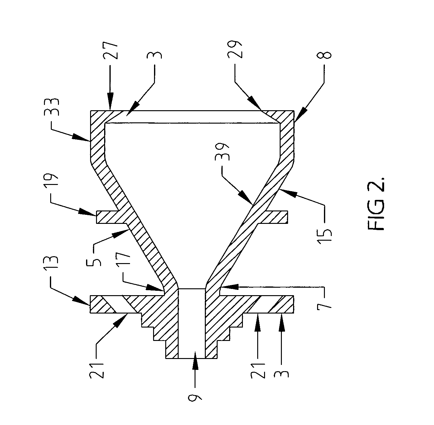
[0036]The preferred embodiments disclose a sound suppressor that utilizes baffles that use one or more of the disclosed features that enhance reduction of sound and flash, these features being a rearward conical protrusion provided with multi-annular steps, a flange with an external diameter slightly less than the internal diameter of the cylindrical housing, a frontal turbulence generation structure, at least one gas port positioned on the baffle, a frontal turbulence generation structure provided with at least one cut-out, and gas cross-flow enhancement cuts positioned on the proximal and distal sides of the baffles. The rearward conical protrusion provided with multi-annular steps may be positioned on the proximal face of a flat baffle or a baffle that uses a flat rear face as a part of the baffle structure or as a part of a conical baffle. The multi-annular steps may also be provided with a tapered section, whereby the tapered surface tapers inward from the outside diameter of e...


PUM


Abstract

A sound suppressor for a firearm for reducing sound and flash levels upon the discharge of a firearm comprises a cylindrical housing, a proximal end cap with means for attachment to a firearm and to the cylindrical housing, a distal end cap with means for attachment to the housing, and a plurality of baffles positioned within the housing and between the proximal end and distal end caps of the suppressor. A separate cylindrical spacer element is positioned between the proximal end cap of the suppressor and the first baffle. This spacer provides axial positioning of the baffles within the cylindrical housing of the suppressor. The distal end cap of the suppressor is provided with a concentric circular hole or aperture for the projectile to pass through the end of the suppressor. In a number of preferred embodiments, the sound suppressor utilizes baffles that use two or more of the disclosed features that enhance reduction of sound and flash, these features being a rearward conical protrusion provided with multi-annular steps, a flange with an external diameter slightly less than the internal diameter of the cylindrical housing, a frontal turbulence generation structure, a frontal turbulence generation structure provided with at least one cut-out, a turbulence generation structure, and gas cross-flow enhancement cuts positioned on the proximal and distal sides of the baffles.

Description

[0001]This application claims priority from the provisional application filed Nov. 5, 2004, Ser. No. 60 / 625,069.BACKGROUND OF THE INVENTION[0002]1. Field of the Invention[0003]The present invention relates to a sound suppressor for a firearm, and more particularly to baffles for use in a sound suppressor for a firearm.[0004]2. Background of the Invention[0005]Sound suppressors for firearms are well known in the prior art, and many have been patented over a considerable period of time. Many different techniques have been developed and patented, and baffles of varying designs have been extensively used. The aim and intention of a sound suppressor, regardless of the technique used, is to reduce the pressure and velocity of the propellant gases from the sound suppressor so that the resulting sound level is significantly reduced.[0006]Quite complex baffle structures are known in the prior art. Some of these baffles have more recently used asymmetric features, such as slanted sidewalls or...

Claims


Application Information

Patent Timeline
IPC IPC(8): F41A21/30F01N1/02F01N1/08
CPCF41A21/30
Inventor HOEL, THOMAS TRAIL
Owner SMITH & WESSON
Why Eureka
Try Eureka