Dosing device for fluids, especially a motor vehicle injection valve

a technology for injecting valves and fluids, which is applied in the direction of valve operating means/release devices, machines/engines, and shock absorbers, etc., can solve the problems of changing the length of actuators, achieve the effect of preventing pressure waves, facilitating very rapid needle closing, and improving the removal of actuators

Inactive Publication Date: 2007-12-18
CONTINENTAL AUTOMOTIVE GMBH
View PDF19 Cites 32 Cited by
  • Summary
  • Abstract
  • Description
  • Claims
  • Application Information

AI Technical Summary

Benefits of technology

[0017]The object of the present invention is to provide a dosing device which meets the described requirements profile as fully as possible and, most especially, allows the hermetic sealing and heat removal from the actuator to be optimized. The advantages of a high degree of hydraulic compressive pre-stressing should be retained and at the same time it must be possible for the optimized length compensator to be integrated into the dosing device overall in a simple manner.
[0018]Said object is achieved according to the invention by a dosing device for dosing a fluid under pressure being dosed, comprising a housing with a dosing aperture which can be controlled by displacement of a valve needle, an electromechanical actuator, whose length can be changed in the axial direction, which is located inside a working chamber of the housing, and whose two end faces are connected one to the valve needle and the other to an axially movable hydraulic piston, a hydraulic chamber hydraulically connected in a throttled manner to the working chamber by means of a first fit between the hydraulic piston and the housing, with the first fit being embodied in such a way that the hydraulic piston will retain its position relative to the housing if there is a rapid change in the length of the actuator, wherein the working chamber and the hydraulic chamber can be filled with a working fluid, the working chamber is divided by a hermetically tight separating membrane into an actuator chamber containing the actuator and a fluid chamber, the fluid chamber can be filled under pressure with the fluid being dosed, while the actuator chamber and the hydraulic chamber are filled with a hydraulic fluid as the working fluid, and wherein a base pressure can be produced in the hydraulic fluid by means of the pressure of the fluid being dosed, said pressure being transmitted through the separating membrane.
[0022]The concept underlying the invention is accordingly based on not directly pressure-filling a working chamber, containing the actuator, with fluid to be dosed, but instead on using the pressure of the fluid to be dosed indirectly—via a pressure-transmitting separating membrane dividing the working chamber into an actuator chamber and a fluid chamber—, in order to subject a hydraulically terminated length compensation system to a very high base pressure. This first enables the hydraulic chamber to accommodate high tensile forces. This facilitates very rapid closing of the needle without the occurrence of cavitation in the hydraulic chamber due to inertial forces. The high base pressure moreover produces ideal hydraulic compressive pre-stressing of the actuator, which is to say a high force with a vanishing spring constant.
[0023]Subjecting the hydraulic compensation system according to the invention indirectly to pressure makes it possible to avoid any disadvantages of direct contact between the actuator and the fluid being dosed or, as the case may be, to gain the advantages that may ensue from surrounding the actuator with a special hydraulic fluid. The silicon oil advantageously surrounding the actuator improves the removal of the actuator's dissipated heat to the housing of the injection valve and to the cylinder head.
[0025]A preferred embodiment can be achieved by routing the valve needle axially in the housing through two narrow needle ducts in the area between the fluid chamber and the dosing aperture, by the valve needle's having flattened sections in the area of the needle duct on the side of the dosing aperture so that the fluid being dosed, which is supplied from a fluid feed, can reach the dosing aperture unimpeded, by embodying the needle duct on the side of the fluid chamber so narrowly as to preclude or allow only a highly throttling hydraulic link between the needle duct on the side of the dosing aperture and the fluid chamber, and by allowing the fluid being dosed to be supplied for the purpose of pressure-filling the fluid chamber via a branch from the fluid feed to said fluid chamber. This will prevent the pressure waves caused by the rapid switching of the valve from propagating into the space above the top needle duct and there damaging, for instance, the axially soft separating membrane.

Problems solved by technology

However, other influencing factors, in particular changes in temperature, also cause changes in the actuator's length, although these take place relatively slowly.

Method used


Image

  • Dosing device for fluids, especially a motor vehicle injection valve
  • Dosing device for fluids, especially a motor vehicle injection valve
  • Dosing device for fluids, especially a motor vehicle injection valve

Examples


Embodiment Construction

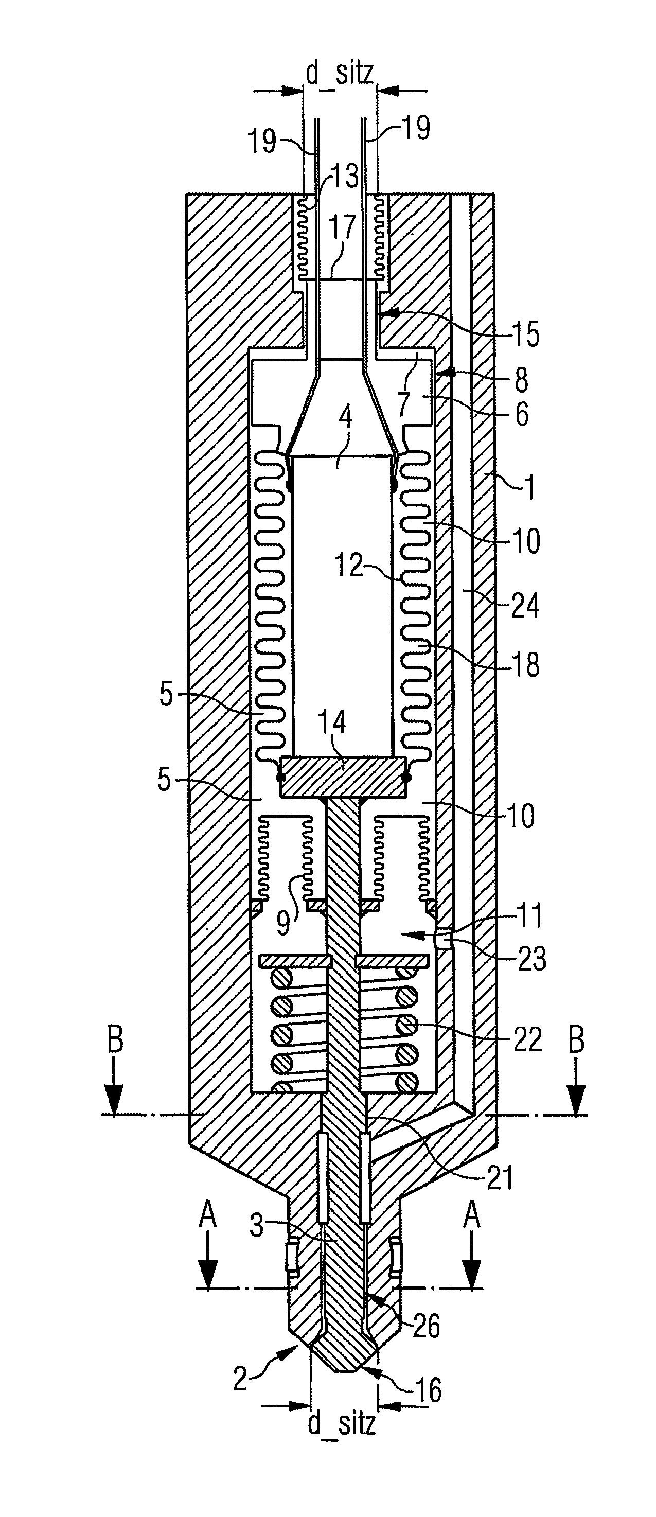
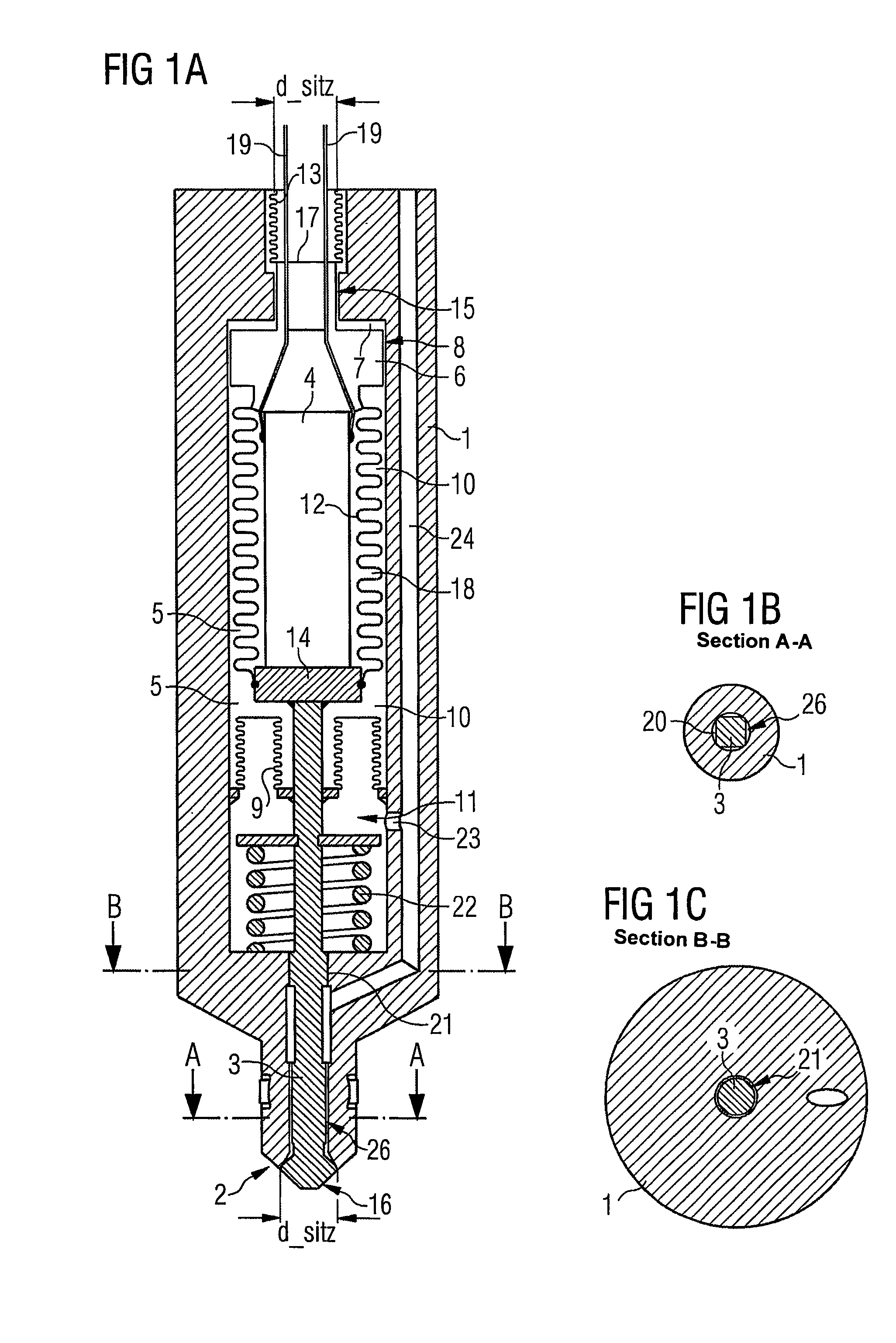
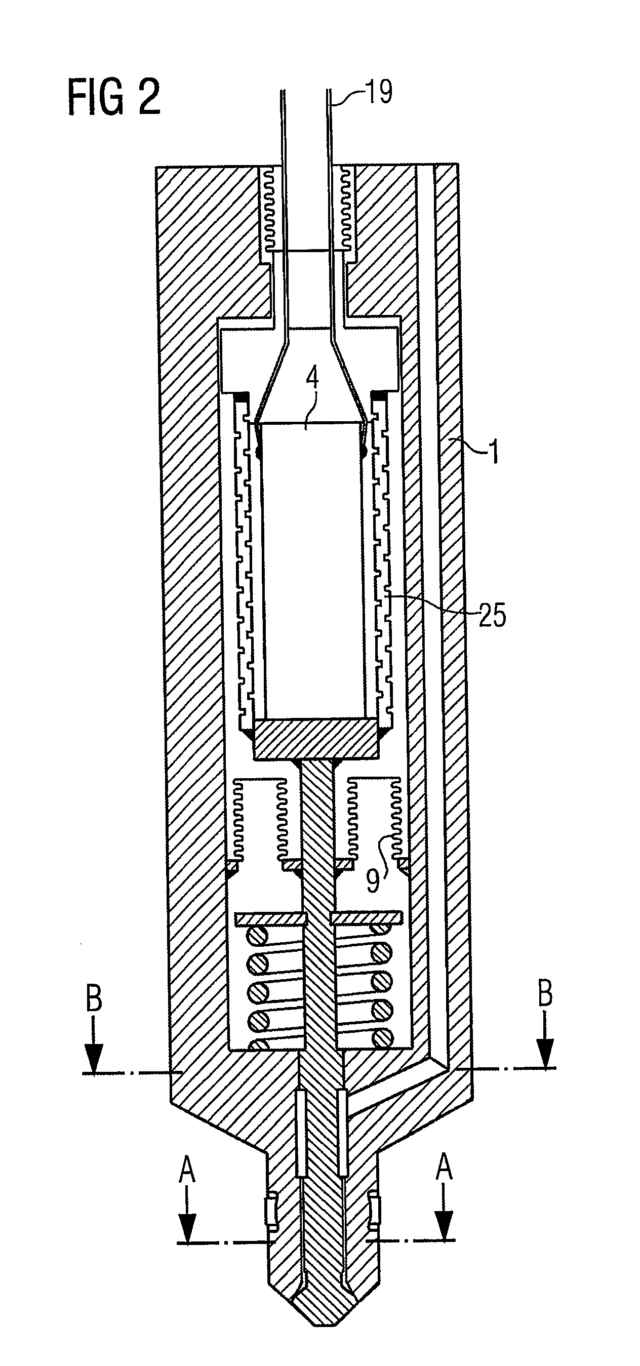
[0031]FIG. 1A is a side view of a housing 1 of an injection valve in cross-section. The dosing aperture 2 is sealed by the valve needle 3; the valve needle 3 and the actuator 4 driving it are in the idle position. The actuator 4 is located within a working chamber 5 of the housing 1 and its end faces are each provided with an end cap, with the top end cap being embodied as an axially movable hydraulic piston 6. Located above the hydraulic piston 6 is the hydraulic chamber 7 which is hydraulically connected in a throttled manner by means of a first fit 8 between the hydraulic piston 6 and the housing 1 to the working chamber 5, with the first fit 8 being embodied in such a way that the hydraulic piston 6 will retain its position relative to the housing 1 if there is a rapid change in the length of the actuator 4.

[0032]The fluid chamber 11 filled with fuel is separated from the actuator chamber 10 filled with silicon oil by means of an axially soft separating membrane 9 which is conne...


PUM


Abstract

An actuator (4) is connected, on one side, to a valve needle (3), and on the opposite side, to a hydraulic piston (6) pertaining to a hydraulic length compensator. A working chamber (5) is divided by a tight separating membrane (9), into an actuator chamber (10) containing the actuator (4) and a fluid chamber (11) which can be filled with the fluid to be dosed in a pressurized manner while the actuator chamber (10) and the hydraulic chamber (7) are filled with a hydraulic fluid. A base pressure can be produced in the hydraulic fluid by means of the pressure of the fluid to be dosed, which is transmitted through the separating membrane (9).

Description

CROSS REFERENCE TO RELATED APPLICATION[0001]This application is a continuation of copending International Application No. PCT / DE03 / 01092 filed Apr. 2, 2003 which designates the United States, and claims priority to German application no. 102 17 882.8 filed Apr. 22, 2002.TECHNICAL FIELD OF THE INVENTION[0002]The present invention relates to a dosing device for dosing a fluid which is under pressure and which is to be dosed. Devices of said type, referred to below also as a dosing or injection valve, have as their main components an electromechanical actuator that drives a valve needle and a hydraulic length compensator, and are used in particular as injection valves for internal combustion engines.DESCRIPTION OF THE RELATED ART[0003]A device of this type is already known from DE 199 40 056 A1.[0004]Increasing use is being made in motor vehicle technology of injection systems in which fuel under high pressure is applied to injection valves located in the cylinders. The process of inje...

Claims


Application Information

Patent Timeline
Patent Type & Authority Patents(United States)
IPC IPC(8): B05B1/30F02M51/00F16K31/02F02M51/06F02M61/08F02M61/16F02M61/20F02M63/00F16K31/00
CPCF02M51/0603F02M61/08F16K31/007F02M61/167F02M2200/16
Inventor FISCHER, BERNHARDGOTTLIEB, BERNHARDKAPPEL, ANDREASULIVIERI, ENRICO
Owner CONTINENTAL AUTOMOTIVE GMBH
Why Eureka
Try Eureka