Radiation imaging apparatus and method of controlling the same
a radiation imaging and apparatus technology, applied in the field of moving radiation imaging apparatuses, can solve the problems of adversely affecting the outer shape of the apparatus, large battery size in view of operationality, and increase in weight and outer dimensions of the battery, so as to reduce the occurrence of unnecessary operations and reduce power consumption.
- Summary
- Abstract
- Description
- Claims
- Application Information
AI Technical Summary
Benefits of technology
Problems solved by technology
Method used
Image

Examples
first embodiment
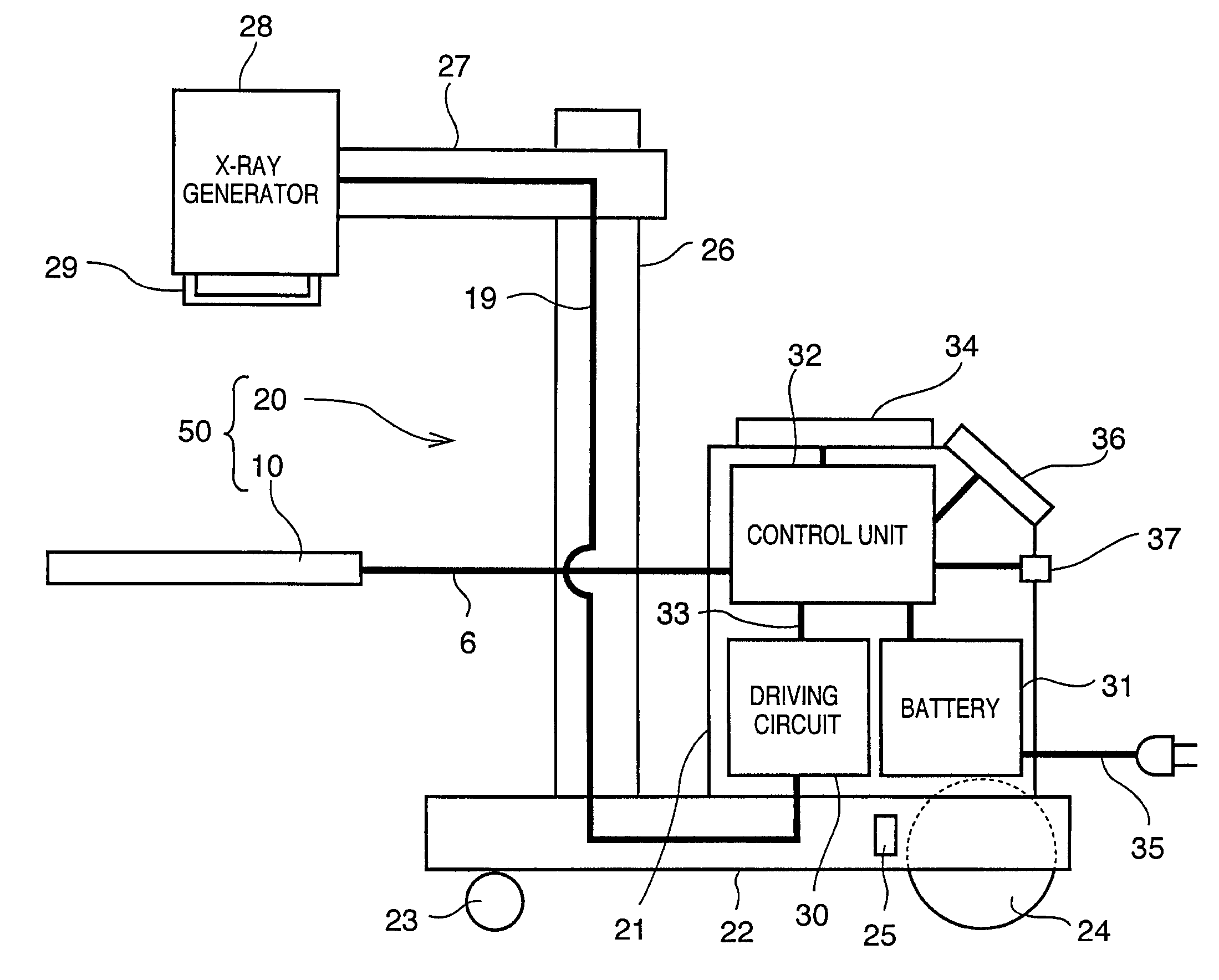
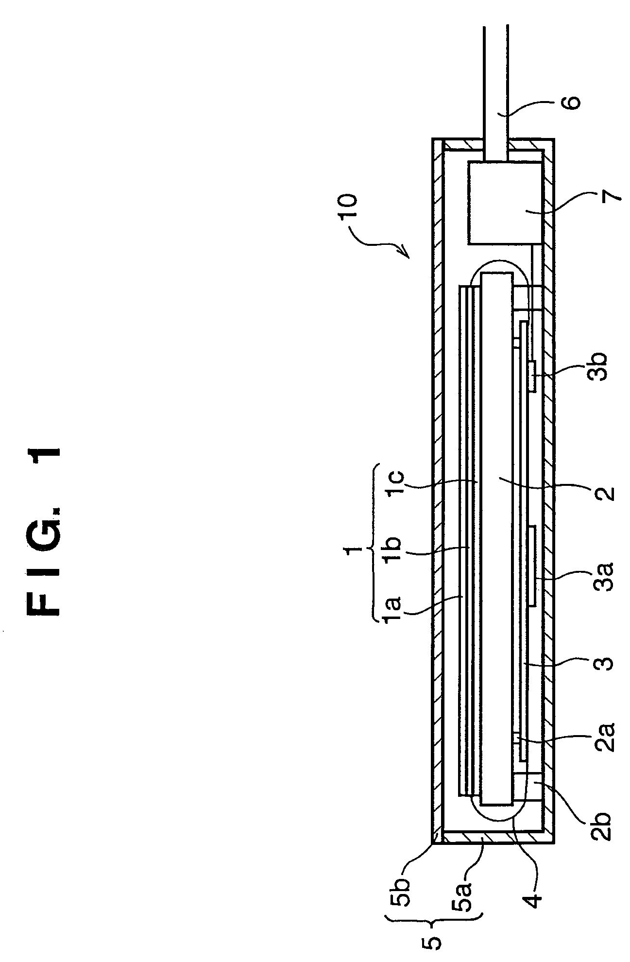
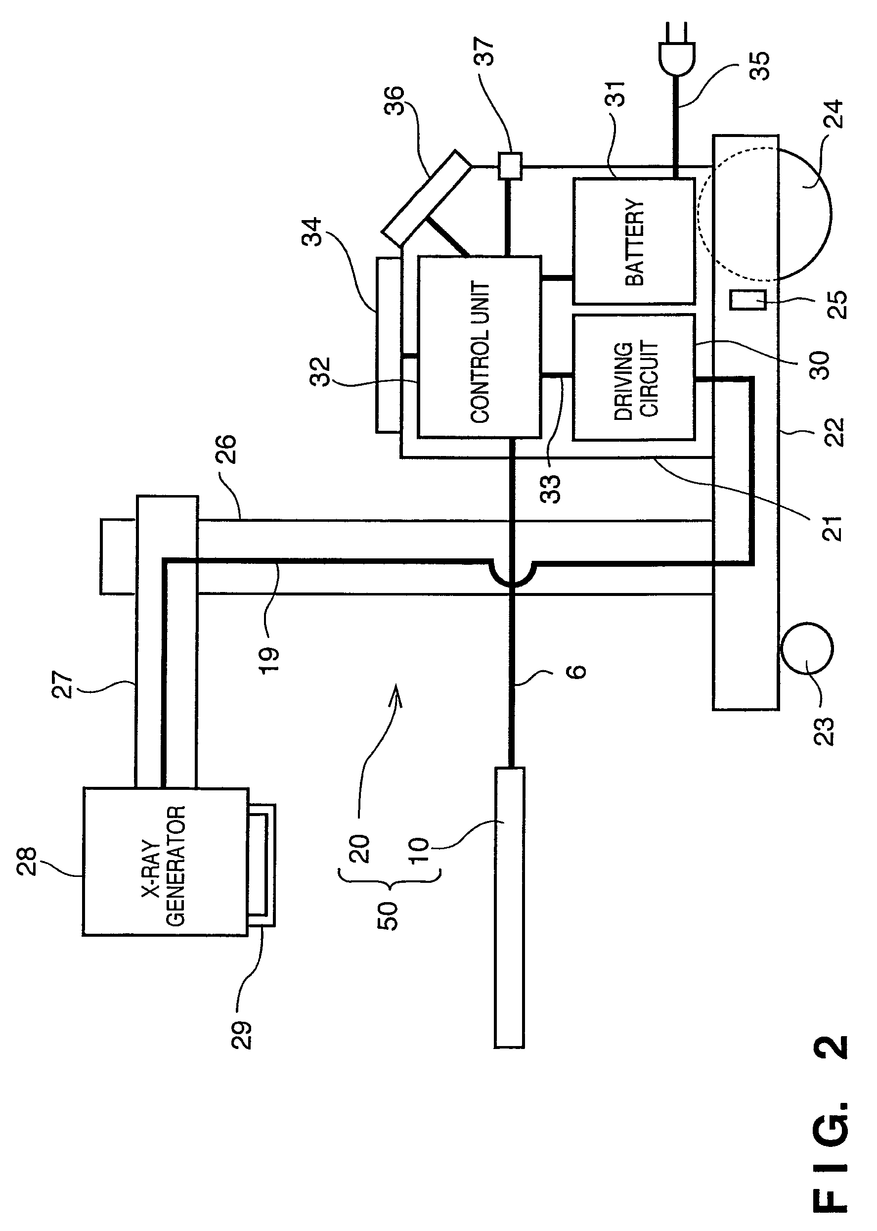
[0025]FIG. 1 is a side sectional diagram showing an imaging unit of the present embodiment. FIG. 2 is a diagram for explaining the configuration of a movable imaging apparatus of the present embodiment. FIG. 3 is a flowchart for explaining the operations of the movable imaging apparatus of the present embodiment.
[0026]In FIG. 1, an X-ray detection panel 1 is mainly constituted of a fluorescent screen 1a, an photoelectronic converter 1b, and a substrate 1c. In many cases, the substrate 1c is a glass plate because the glass plate causes no chemical action with a semiconductor element, the glass plate is resistant to the temperature of a semiconductor process, and dimensional stability and so on are necessary. The photoelectronic converter 1b is formed in a two-dimensional array on the glass substrate 1c according to a semiconductor process. The fluorescent screen 1a is formed by applying a phosphor of a metal compound to a resin plate, and integrated with the substrate 1c by bonding.
[...
second embodiment
[0051]The first embodiment described the configuration in which the first operating unit 34 for setting and driving the X-ray generator 28 and the imaging unit 10 and the second operating unit 36 for displaying management information are separated. The advantages of the separated first and second operating units were already described above. When greater importance is placed on cost than these advantages, the operating units may be configured as a single unit. An example of a second embodiment will describe that a power saving is achieved and an operating error is prevented in such cases.
[0052]FIG. 4 is a schematic structural diagram for explaining the configuration of a movable imaging apparatus 51 according to the second embodiment. The second embodiment is similar to the first embodiment except that the first operating unit 34 and the second operating unit 36 of the first embodiment are configured as one operating unit 40. The operating unit 40 has a display device as an output u...
third embodiment
[0055]In the second embodiment, when the apparatus is in a moving state, an operating error is prevented by switching the screens with the single operating unit 40. In a third embodiment, one screen is divided into two or more areas one of which does not accept an operation input when a movable imaging apparatus is in a moving state, thereby preventing an operating error.
[0056]FIG. 6 is a diagram showing a display example of an input / output device 40 of the third embodiment. In the example of FIG. 6, a screen on a display device is divided into a display area 47 and a display area 48. The display area 47 displays a screen for operating an X-ray generator 28 and an imaging unit 10 and the display area 48 displays a list of patient information (list display in FIG. 10A) based on management information. When a movement of the movable imaging apparatus is detected, output to the first display area is automatically turned off to prevent reaction to input. Only the display area 47 may act...
PUM
 Abstract
Description
Claims
Application Information
 - R&D
- Intellectual Property
- Life Sciences
- Materials
- Tech Scout
- Unparalleled Data Quality
- Higher Quality Content
- 60% Fewer Hallucinations
Browse by: Latest US Patents, China's latest patents, Technical Efficacy Thesaurus, Application Domain, Technology Topic, Popular Technical Reports.
© 2025 PatSnap. All rights reserved.Legal|Privacy policy|Modern Slavery Act Transparency Statement|Sitemap|About US| Contact US: help@patsnap.com