Polymeric injection mold with retractable bars for producing re-entrant molded surfaces

a technology of re-entrant molded surfaces and injection molds, which is applied in the direction of dough shaping, application, manufacturing tools, etc., can solve the problem that the mold cannot be easily separated

Inactive Publication Date: 2007-12-18
PIERSON INDS
View PDF26 Cites 7 Cited by
  • Summary
  • Abstract
  • Description
  • Claims
  • Application Information

AI Technical Summary

Benefits of technology

[0022]The clearance between the slide bars and the rectangular slots is small enough to prevent the leakage of the plasticized polymer. This clearance is typically in the range of 0.0005″ to 0.001″. Material selection and temperature of the mold also act in determining the appropriate clearance value. The rectangular slots are inclined to the centerline of the mold. The direction of this inclination is directly related to the orientation of the re-entrant surface, such that the direction in which the slide bar projection must be moved will allow the slide bar projection to clear the re-entrant surface of the injection molded polymeric part. If the re-entrant surface faces downwardly towards the centerline of the mold, the rectangular slots are also inclined towards the centerline. On the other hand, if the re-entrant surfaces face away from the centerline, the rectangular slots are inclined away from the centerline. Typical angle of inclination is in the range of 1 to 45 degrees, and more preferably in the range of 10-15 degrees.
[0023]Generally stated, the present invention relates to a polymeric injection mold with retractable slide bars for producing re-entrant molded surfaces on both sides of the parting line. In one embodiment, a polymeric frame having re-entrant surfaces on both its upper and lower portions and on both sides of the parting line is injection molded in a single step without elaborate multiple steps of removing additional cam action bars that define the re-entrant surfaces. The polymeric injection mold of the present invention has retractable slide bar projections inserted in both the stationary ‘A’ side of the injection mold and the movable ‘B’ side of the injection mold. The slide bar projections are permanently attached to the slide bars, which pass through rectangular slots in the stationary part and the movable part, respectively, of the mold. The clearance between the slide bars and the corresponding rectangular slot in the mold is generally small, typically 0.0005″ to 0.001″, so that the injected polymer does not leak through, but the clearance is large enough to allow for the free movement of the slide bars within the rectangular slots. The rectangular slots are inclined to the mold at a preferred angle of 10 to 15 degrees with an orientation that matches the orientation of the re-entrant surface. As a result, the movement of the slide bars within the rectangular slots displaces the slide bar projections in a direction such that the slide bar projections will clear the re-entrant surfaces in the molded polymeric part.
[0025]Next, the ejection sequence is activated which essentially actuates an ejector plate in order to push the slide bars on the movable side of the mold. This pushing action causes the slide bars to move within the rectangular slots in order to withdraw the slide bar projections on the movable side of the mold from the re-entrant surfaces of the injection molded polymeric part. The functionality of this step of the process is similar to that used in the stationary part of the mold. The slide bars pass through the rectangular slots in the movable side of the mold at an inclination to the centerline, thereby displacing the slide bar projections in the movable part of the mold clearing the re-entrant surfaces. At this stage, the polymeric injection molded part is free from both the stationary side and the movable side of the mold, and can therefore be removed.
[0028]b) the mold cavity having tapered mold surfaces for easy release of the molded part;

Problems solved by technology

If this taper is not present, the mold cannot be easily separated.

Method used


Image

  • Polymeric injection mold with retractable bars for producing re-entrant molded surfaces
  • Polymeric injection mold with retractable bars for producing re-entrant molded surfaces
  • Polymeric injection mold with retractable bars for producing re-entrant molded surfaces

Examples


Embodiment Construction

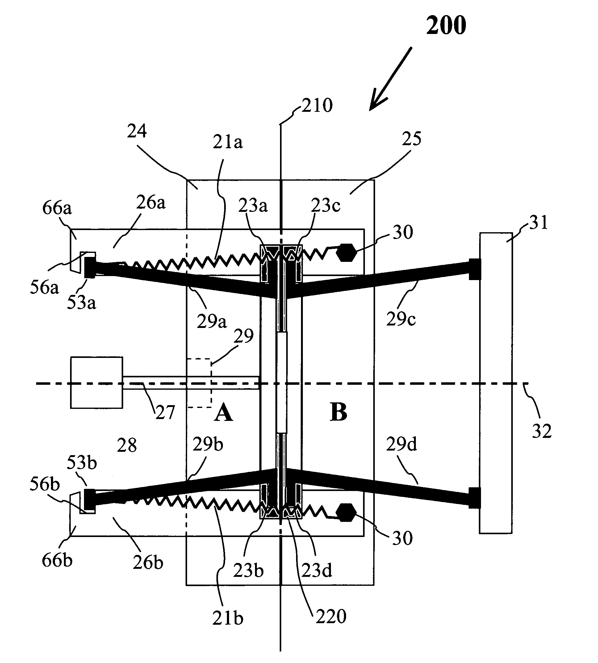
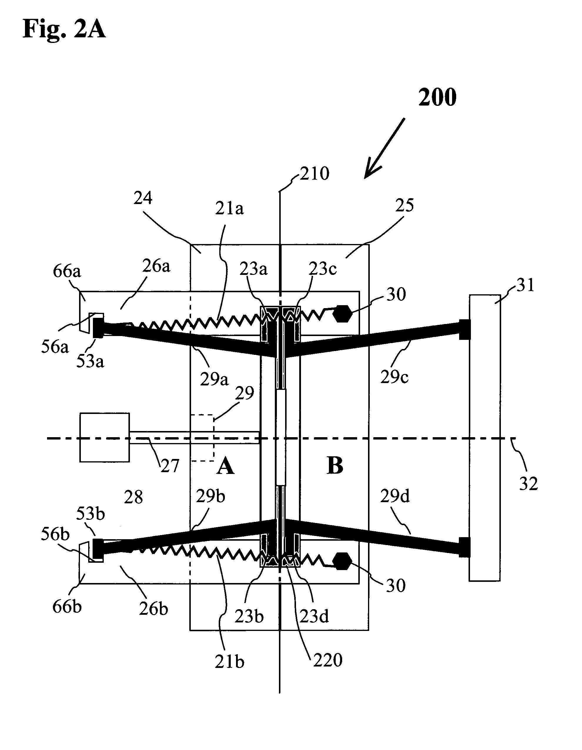
[0042]Injection molding of polymeric components is easily accomplished by injecting a molten polymer into a mold which has two mating mold halves with a parting line there between. The polymer from the injection molding machine is injected through one half of the mold, which is rigidly attached to the injection molding machine, called the ‘A’ side or the stationary part of the mold. The other side of the mold, the ‘B’ side or the movable part of the mold is movable, wherein the subsequent separation of the mold and actuation of a knock-out plate allows removal of the injection molded polymeric part. The injection mold is typically designed with each surface of the molded part tapered so that the molded part separates easily at the end of molding operation from the mold cavity. Typically, this separation generally requires that the interior surfaces of the mold are not re-entrant. However, there are circumstances when the injection molded polymeric part requires re-entrant surfaces, ...


PUM

PropertyMeasurementUnit
angleaaaaaaaaaa
angleaaaaaaaaaa
angleaaaaaaaaaa

Abstract

A polymeric injection mold has stationary and movable parts mating at a parting line. The polymeric part has one or more re-entrant surfaces on both sides of the parting line, wherein the re-entrant surfaces are defined by slide bar projections inserted into the mold. The slide bar projections are attached to slide bars that pass through tapered slots in the side walls of the stationary and movable sides of the mold and are inclined at an angle to the centerline of the mold. The slide bars of the stationary side of the mold are removably connected to pull bars, wherein the pull bars are rigidly attached at their opposite ends to the movable side of the mold. When the movable side of the mold is withdrawn, the injection molded part is pulled out of the stationary side of the mold when the slide bar projections clear the re-entrant surfaces.

Description

BACKGROUND OF THE INVENTION[0001]1. Field of the Invention[0002]The present invention relates to a polymeric injection mold for producing re-entrant molded surfaces and more particularly to a molding process and device for producing a molded article having re-entrant surfaces.[0003]2. Description of the Prior Art[0004]Many patents address issues related to injection molding of polymeric articles. The patents and publications that relate to polymeric injection molding with re-entrant surfaces are discussed hereinbelow.[0005]U.S. Pat. No. 3,910,748 to Kopernik discloses plastic mold construction in which foamed thermoplastic articles, particularly elongated boards can be produced at a high rate of production. The mold may be selectively provided with different ornamental surface designs. The mold comprises a stationary match plate member and one or more movable plate members arranged for cooperation with the stationary match plate. One or more elongated ejector bars are slidably arran...

Claims


Application Information

Patent Timeline
Patent Type & Authority Patents(United States)
IPC IPC(8): B29C45/44
CPCB29C45/44Y10S425/058
Inventor PIERSON, THEODORE J.CARLE, RICHARD J.
Owner PIERSON INDS
Why Eureka
Try Eureka