
Heat sink for integrated circuit devices

a technology of integrated circuit devices and heat sinks, which is applied in the direction of resistor details, solid-state devices, thin film varistors, etc., can solve the problems of heat generation, negative influence of certain electrical characteristics, and devices in integrated circuits that are susceptible to heat, etc., and achieve high thermal conductivity, high thermal conductivity, and high thermal conductivity

Active Publication Date: 2007-12-18
INT BUSINESS MASCH CORP
View PDF13 Cites 2 Cited by
  • Summary
  • Abstract
  • Description
  • Claims
  • Application Information

AI Technical Summary

Benefits of technology

The invention relates to a heat sink, resistor, thermal interface, and method of cooling a resistor. The technical effects include improved heat transfer and reduced temperature gradients, which can improve the performance and reliability of electronic components. The heat sink includes a high thermal conductivity insulator and electrical conductor in thermal contact with the insulator, while the resistor includes a high thermal conductivity insulator and electrical conductor in thermal contact with the insulator. The method involves forming the insulator and conductor in the substrate and adjacent to the resistive pathway, allowing for improved heat transfer and reduced temperature gradients.

Problems solved by technology

Also, some devices in integrated circuits are susceptible to heat and may have certain electrical characteristics negatively influenced by heating.
Heating effects can be especially harmful to high precision devices, where the heating effects ruin the precision with which the particular device operates.
For example, a high precision resistor, which is designed to carry a relatively large amount of current, will generate substantial amounts of heat.
The self-heating effects experienced by an integrated circuit device can be further exacerbated by the integrated circuit device being surrounded by a poor heat conductor which impedes heat dissipation.
Typically, electrical insulators which also have poor heat conduction properties surround many integrated circuit devices.
Thus, the design of many integrated circuit devices increase the devices susceptibility to the negative effects of self-heating.
Additionally, contacting an electrically conducting thermal conductor to an electrical device and a heat sink will typical short the electrical device to ground.

Method used


Image

  • Heat sink for integrated circuit devices
  • Heat sink for integrated circuit devices
  • Heat sink for integrated circuit devices

Examples


Embodiment Construction

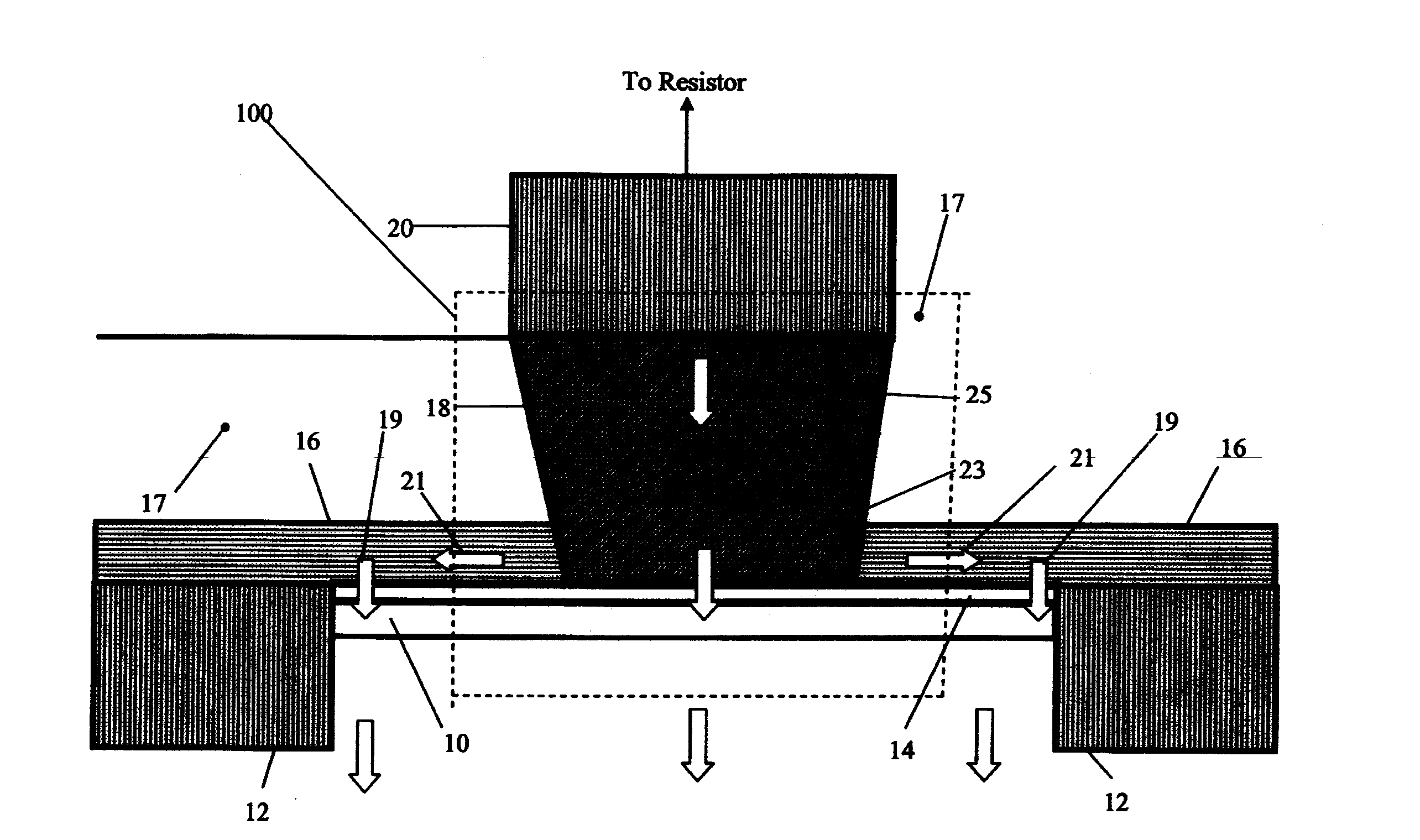
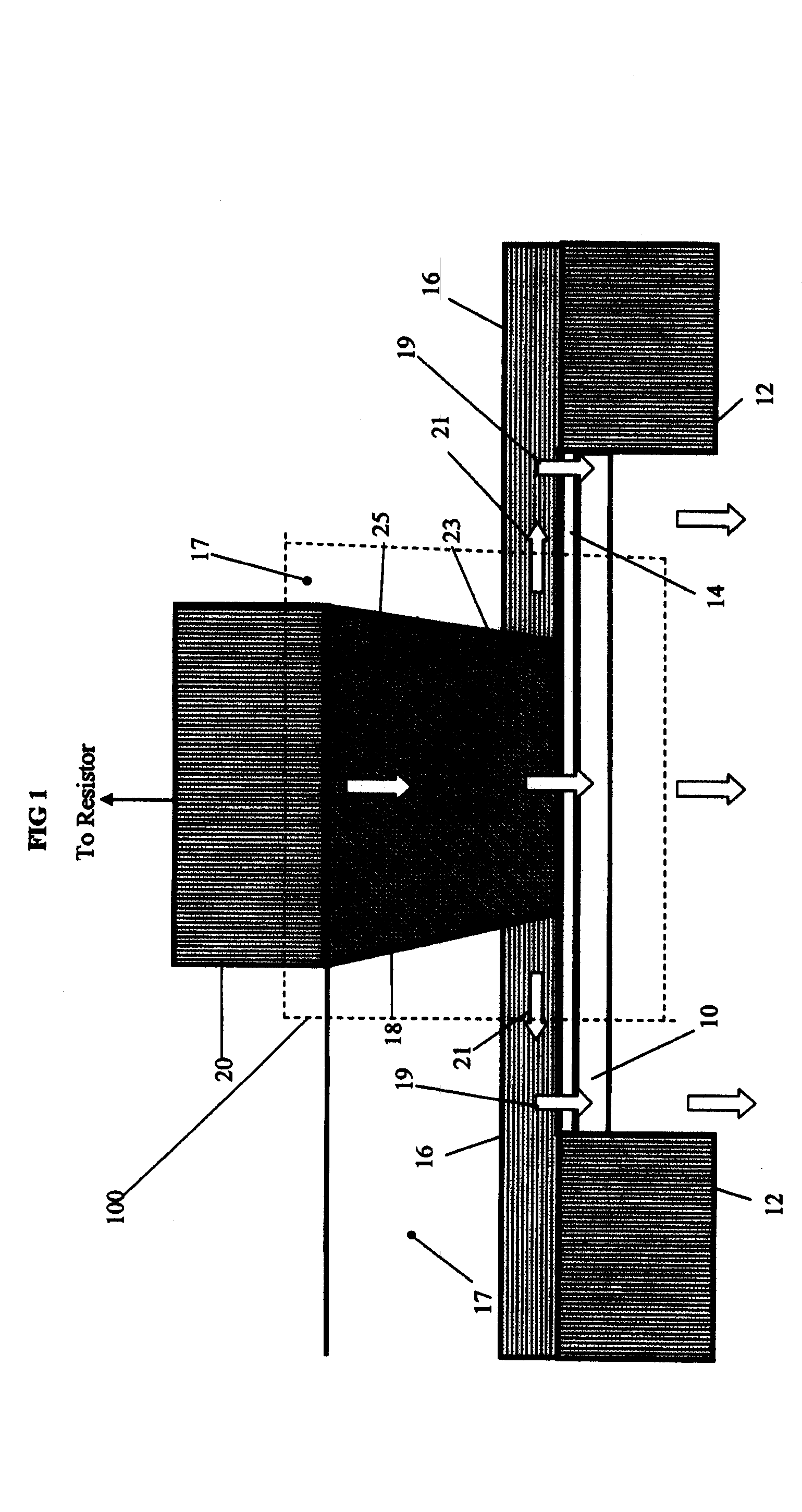
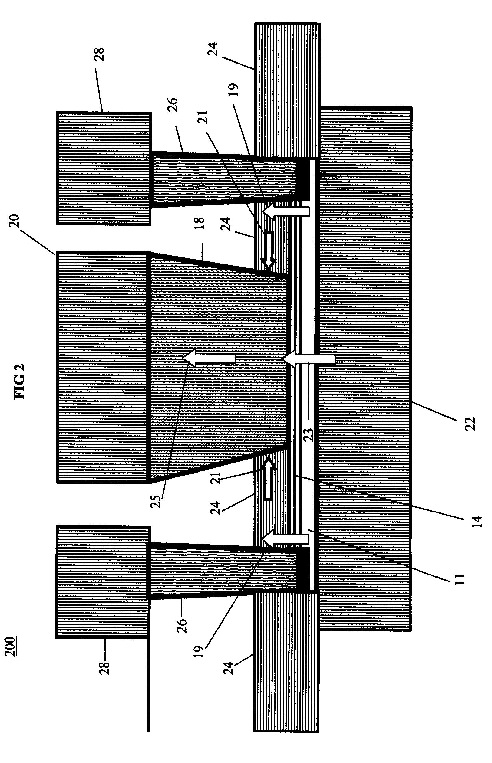
[0020]The invention relates to, for example, heat sinks for integrated circuit devices such as resistors including precision resistors. In embodiments of the invention, a heat sink contact is arranged next to a conductive substrate or thermal conductor having good thermal conductivity in addition to being able to conduct electricity with a relatively thin layer of high thermal conductivity electrical insulator therebetween. The thermal conductor forms an efficient thermal pathway to a heat sink, and because a high thermal conductivity electrical insulator is interposed between the electrical resistor and heat sink contact, the heat sink contact may be made from a metal or other electrical conductor with good heat conduction properties. This provides good thermal conduction without electrically shorting the electrical resistor to ground. The heat sink contact thermal conductor provides enhanced cooling for the electrical resistor, allowing the electrical resistor to conduct higher le...


PUM

PropertyMeasurementUnit
thermal conductivityaaaaaaaaaa
electrically resistiveaaaaaaaaaa
thermalaaaaaaaaaa

Abstract

A resistor with heat sink is provided. The heat sink includes a conductive path having metal or other thermal conductor having a high thermal conductivity. To avoid shorting the electrical resistor to ground with the thermal conductor, a thin layer of high thermal conductivity electrical insulator is interposed between the thermal conductor and the body of the resistor. Accordingly, a resistor can carry large amounts of current because the high conductivity thermal conductor will conduct heat away from the resistor to a heat sink. Various configurations of thermal conductors and heat sinks are provided offering good thermal conductive properties in addition to reduced parasitic capacitances and other parasitic electrical effects, which would reduce the high frequency response of the electrical resistor.

Description

FIELD OF THE INVENTION[0001]The invention relates to heat sinks, and more particularly to heat sinks for integrated circuit devices such as resistors including precision resistors.BACKGROUND DESCRIPTION[0002]In operation of an integrated circuit, some of the devices in the integrated circuit will generate heat. This is particularly true for some types of devices, including, for example, resistors. Also, some devices in integrated circuits are susceptible to heat and may have certain electrical characteristics negatively influenced by heating. Heating effects can be especially harmful to high precision devices, where the heating effects ruin the precision with which the particular device operates.[0003]For example, a high precision resistor, which is designed to carry a relatively large amount of current, will generate substantial amounts of heat. The heat generated by the precision resistor will heat the resistor itself (“self-heating”) thereby altering the resistance of the high pr...

Claims


Application Information

Patent Timeline
Patent Type & Authority Patents(United States)
IPC IPC(8): H01C1/08
CPCH01C1/084H01C7/1013H01L2924/0002Y10T29/49144Y10T29/49147Y10T29/49099Y10T29/49083Y10T29/49085H01L2924/00
Inventor COOLBAUGH, DOUGLAS D.ESHUN, EBENEZER E.HOOK, TERENCE B.RASSEL, ROBERT M.SPROGIS, EDMUND J.STAMPER, ANTHONY KMURPHY, WILLIAM J.
Owner INT BUSINESS MASCH CORP
Learn More