Magnetoresistive sensor having cobalt-iron alloy layer in free layer

a technology of magnetoresistance sensor and free layer, which is applied in the field of magnetoresistance sensor, can solve the problems of inconvenient thickening of free layer, inability to provide sufficient change of magnetoresistance of cpp-gmr sensor, and inability to clarify, etc., and achieves the effect of increasing the soft magnetic characteristics of free layer and reducing the number of changes

Active Publication Date: 2007-12-18
TDK CORPARATION
View PDF7 Cites 8 Cited by
  • Summary
  • Abstract
  • Description
  • Claims
  • Application Information

AI Technical Summary

Benefits of technology

[0011]It is an object of the present invention to provide a magnetoresistive sensor which excels in the soft magnetic characteristics of a free layer, and is capable of accomplishing a larger change in magnetoresistance. It is another object of the present invention to provide a thin-film magnetic head etc. which use the magnetoresistive sensor.
[0013]In the magnetoresistive sensor configured as described above, by providing the free layer with the intermediate stack having the non-magnetic layer sandwiched by cobalt iron alloy layers on the boundaries on both sides, the spin polarizability is increased at the boundaries of the non-magnetic layer, resulting in an increased magnetoresistive effect. Also, by sandwiching the intermediate stack with nickel iron alloy layers, the soft magnetic characteristics are improved. Consequently, the resulting magnetoresistive sensor can present a larger change in magnetoresistance and good soft magnetic characteristics. Also, by inserting the cobalt iron alloy layer on the boundary of the stack composed of the intermediate stack and the nickel iron alloy layers on the side of the spacer layer, it is possible to enhance the boundary scattering effect, thereby limiting diffusion with the spacer layer, causing an increase in the bulk scattering effect.
[0017]As described above, according to the present invention, the magnetoresistive effect is improved by the free layer which contains the intermediate stack having the non-magnetic layer sandwiched by the nickel iron alloy layers on both the boundaries, and the soft magnetic characteristics are improved by sandwiching this intermediate stack with the nickel iron alloy layers. Consequently, the present invention can provide a magnetoresistive sensor which is further improved in the magnetic characteristics required for a free layer of a CPP-GMR sensor and excels in the quality of reproduced output.

Problems solved by technology

However, if an SV film having a stack configuration similar to that of a CIP-GMR sensor is simply applied to a CPP-GMR sensor, the resulting CPP-GMR sensor cannot provide a sufficient change in magnetoresistance.
In order to increase the sensitivity, the direction of magnetization of the free layer must be rotated with a limited amount of magnetic flux of a recording medium, so that a thicker free layer is not desirable.
Also, while the above-mentioned specifications etc. disclose a general layer configuration for a free layer which exhibits a larger change in magnetoresistance, they do not clarify a preferred layer configuration in consideration of the characteristic of change in magnetoresistance, and soft magnetic characteristics such as magnetostriction.

Method used


Image

  • Magnetoresistive sensor having cobalt-iron alloy layer in free layer
  • Magnetoresistive sensor having cobalt-iron alloy layer in free layer
  • Magnetoresistive sensor having cobalt-iron alloy layer in free layer

Examples


Embodiment Construction

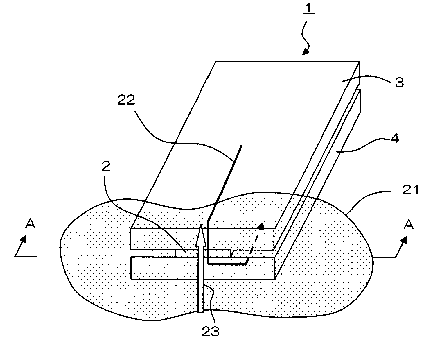
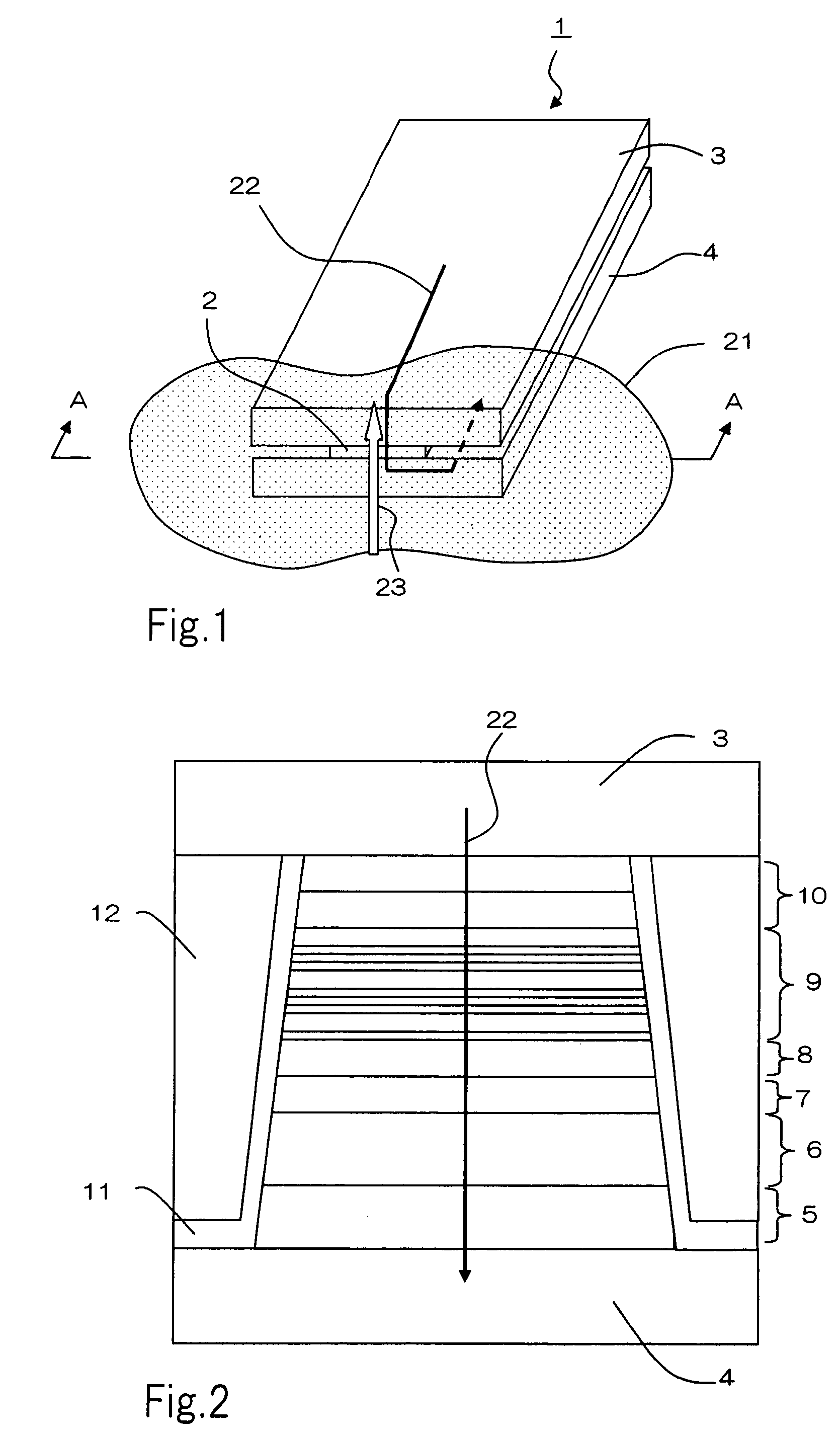
[0028]One embodiment of a magnetoresistive sensor (hereinafter referred to as “CPP sensor 2”) according to the present invention will be described with reference to the accompanying drawings. FIG. 1 is a partial perspective view of thin-film magnetic head 1 which employs the magnetoresistive sensor of the present invention. Thin-film magnetic head 1 may be a read only head, or a MR / inductive composite head which additionally has a write head portion. CPP sensor 2 is sandwiched between upper electrode / shield 3 and lower electrode / shield 4, with one end facing opposite to recording medium 21. Sense current 22, generated by a voltage applied between upper electrode / shield 3 and lower electrode / shield 4, flows from upper electrode / shield 3 to lower electrode / shield 4 through CPP sensor 2 in the direction of stacking, as indicated by an arrow in FIG. 1. A magnetic field of recording medium 21 opposite to CPP sensor 2 changes as recording medium 21 moves in recording medium moving directi...


PUM

PropertyMeasurementUnit
thicknessaaaaaaaaaa
thicknessaaaaaaaaaa
thicknessaaaaaaaaaa

Abstract

A magnetoresistive sensor comprises a pinned layer having a magnetization direction fixed with respect to an external magnetic field, a free layer, having a magnetization direction variable in accordance with the external magnetic field, and a spacer layer mainly containing copper, sandwiched between the pinned layer and the free layer. A sense current flows through the pinned layer, the spacer layer, and the free layer substantially in a direction in which the layers are stacked. The free layer comprises at least one intermediate stack composed of a non-magnetic layer mainly containing copper, and a first cobalt iron layers made of a cobalt iron alloy and disposed on boundaries on both sides of the non-magnetic layer, a nickel iron alloy layers disposed on boundaries on both sides of the intermediate stack, and a second cobalt iron layer made of a cobalt iron alloy and formed in contact with the spacer layer on a boundary, opposing the spacer layer, of a stack composed of the intermediate stack and the nickel iron alloy layer.

Description

BACKGROUND OF THE INVENTION[0001]1. Field of the Invention[0002]The present invention relates to a magnetoresistive sensor, a thin-film magnetic head, a head gimbal assembly, and a hard disk device, and more particularly, to a magnetoresistive sensor for use in thin-film magnetic heads of magnetic storage apparatuses such as a hard disk device and the like.[0003]2. Description of the Related Art[0004]To accommodate the trend of increasingly higher a real density for magnetic recording, magnetic heads using GMR (Giant Magnetoresistive) sensors have been developed for use as a read element. Among others, a GMR sensor using a spin valve (SV) film can provide a magnetic head having a higher sensitivity by virtue of its large change in magnetoresistance to a sense current applied to the device for reading data recorded on a recording medium. Here, the SV film refers to stacked layers which comprise a ferromagnetic layer that has the direction of magnetization fixed in one direction (here...

Claims


Application Information

Patent Timeline
Patent Type & Authority Patents(United States)
IPC IPC(8): G11B5/127G11B5/39H01F10/14H01F10/16H01F10/32H01L43/08
CPCB82Y10/00G11B5/3906B82Y25/00G11B2005/3996
Inventor MIYAUCHI, DAISUKEMIZUNO, TOMOHITO
Owner TDK CORPARATION
Why Eureka
Try Eureka