Method of producing magnetic head and magnetic head

Inactive Publication Date: 2007-09-20
FUJITSU LTD
View PDF2 Cites 2 Cited by
  • Summary
  • Abstract
  • Description
  • Claims
  • Application Information

AI Technical Summary

Benefits of technology

[0021]In the method of the present invention, the cap layer is formed on the surface of the seed layer. Therefore, even if the seed layer made of Ru, which easily varies deposition rate of the magnetic film, is used, the magnetic film can be stably plated and a thickness of the magnetic film can be precisely controlled. By precisely controlling the thickness of the magnetic film, the function of impro

Problems solved by technology

Namely, the nonmagnetic materials other than R

Method used


Image

  • Method of producing magnetic head and magnetic head
  • Method of producing magnetic head and magnetic head
  • Method of producing magnetic head and magnetic head

Examples


Embodiment Construction

[0031]Preferred embodiments of the present invention will now be described in detail with reference to the accompanying drawings.

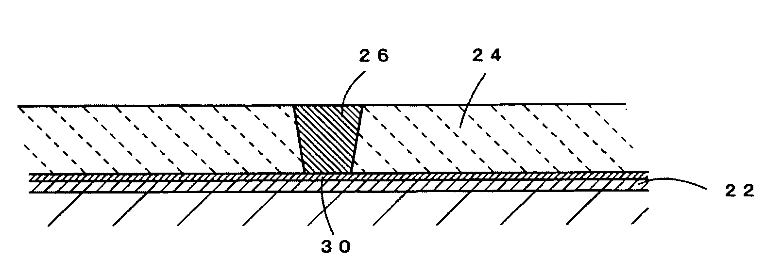
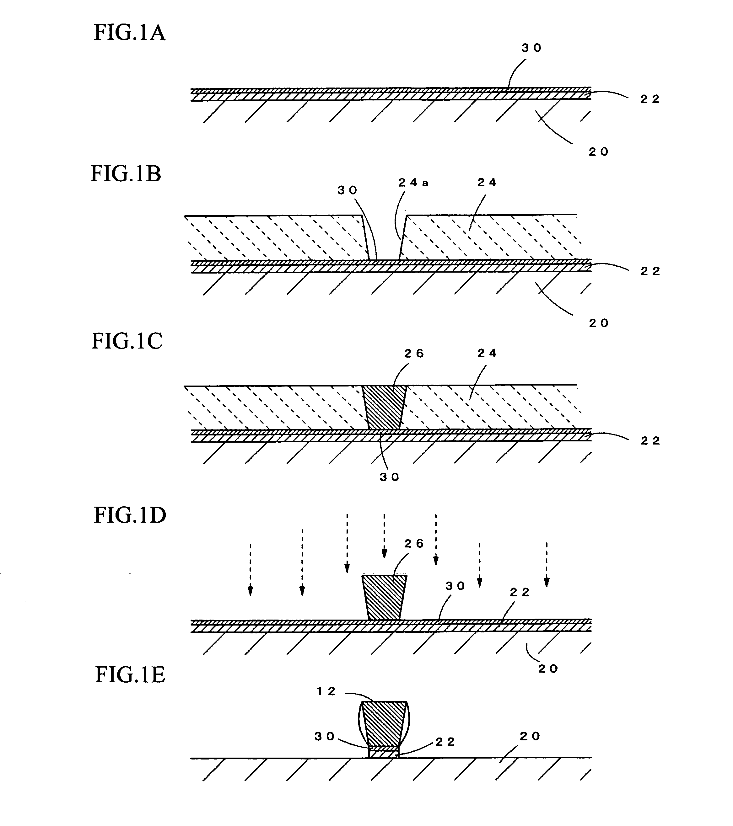
[0032]The method of the present invention, in which a magnetic pole of a write-head of a magnetic head, e.g., a main magnetic pole of a perpendicular magnetic head, is formed by plating, is characterized by: using Ru as a seed layer for plating; forming a cap layer, which is made of an electrically conductive material, after forming the Ru seed layer; and forming a magnetic film, which acts as a magnetic pole. Firstly, a production process of the magnetic head of the present invention will be explained with reference to FIGS. 1A-1E.

[0033]In FIG. 1A, a seed layer 22 for plating is formed on a surface of a wafer 20, which is a work piece on which films will be formed, so as to form a magnetic film 26, which acts as a magnetic pole, on the work piece 20. Further, a cap layer 30, which is made of an electrically conductive material, is formed on a surface of t...


PUM

PropertyMeasurementUnit
Thicknessaaaaaaaaaa
Electrical conductivityaaaaaaaaaa
Magnetismaaaaaaaaaa

Abstract

The a method of producing a magnetic head is capable of stabilizing deposition rate of a plated magnetic film forming a magnetic pole of a write-head. The method of producing a magnetic head, in which a magnetic pole of a write-head is constituted by a magnetic film, comprises the steps of: forming a seed layer made of Ru on a surface of a work piece; forming a cap layer on a surface of the seed layer so as to stabilize deposition rate of the magnetic film; and forming the magnetic film by electrolytic plating, and the seed layer and the cap layer are used as power feeding layers for the electrolytic plating.

Description

BACKGROUND OF THE INVENTION[0001]The present invention relates to a method of producing a magnetic head and a magnetic head, more precisely relates to a method of producing a magnetic head, which is characterized by a process of forming a write-head, and a magnetic head produced by said method.[0002]A conventional perpendicular (vertical) magnetic head is shown in FIG. 7. The perpendicular magnetic head comprises: a read-head 8, in which an MR element 6 for reproducing data is sandwiched between a lower shielding layer 5 and an upper shielding layer 7; and a write-head 10, in which a write-gap 13 is sandwiched between a main magnetic pole 12 and a return yoke 14. A symbol 15 stands for a coil for writing data.[0003]The magnetic pole 12 of the write-head 10 is constituted by a magnetic film. An end face of the magnetic pole 12, which faces a recording medium, is made narrow so as to converge magnetic fluxes and has a film thickness of 3-4 μm. The magnetic pole is formed by plating, s...

Claims


Application Information

Patent Timeline
IPC IPC(8): G11B5/147G11B5/127
CPCC25D5/022C25D5/54Y10T29/49021G11B5/3116G11B5/3163G11B5/1871
Inventor MIYAKE, YUKOMATSUOKA, MASAAKI
Owner FUJITSU LTD
Why Eureka
Try Eureka