Perpendicular magnetic recording medium and magnetic recording/reproducing apparatus using the same

a technology of magnetic recording medium and magnetic recording/reproducing apparatus, which is applied in the direction of magnetic recording, data recording, instruments, etc., can solve the problems of difficult to completely eliminate the exchange interaction between the magnetic grains, and achieve the effect of high-density recording and accurate control of the magnetization reversal

Active Publication Date: 2009-08-06
WESTERN DIGITAL TECH INC
View PDF17 Cites 29 Cited by
  • Summary
  • Abstract
  • Description
  • Claims
  • Application Information

AI Technical Summary

Benefits of technology

[0010]Embodiments of the present invention provide accurate control of the magnetization reversal in a magnetic recording layer in small reversal units, whereby high-density recording can be achieved. According to the embodiment of FIG. 1, by forming an intermediate layer 14 having a granular structure similar to that of the magnetic recording layer 15 below the magnetic recording layer, a continuous crystal grain boundary is formed at the interface between the magnetic recording layer 15 and the intermediate layer 14, thereby preventing incomplete formation of the crystal grain boundary found in the initial growth layer of the magnetic recording layer 15. The intermediate layer 14 comprises a non-magnetic alloy comprising Co and Cr as its main components and an oxide such as Al, Cr, Hf, Mg, Nb, Si, Ta, Ti and Zr. Further, the average content of the oxygen element in the intermediate layer 14 is in the range from 6 at % to 20 at %.

Problems solved by technology

However, it is difficult to completely eliminate the exchange interactions between the magnetic grains, and the magnetization reversal unit in the magnetic recording layer tends to be larger than the average grain size of the magnetic grains.

Method used


Image

  • Perpendicular magnetic recording medium and magnetic recording/reproducing apparatus using the same
  • Perpendicular magnetic recording medium and magnetic recording/reproducing apparatus using the same
  • Perpendicular magnetic recording medium and magnetic recording/reproducing apparatus using the same

Examples


example 1

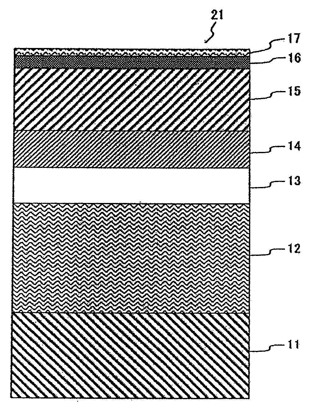
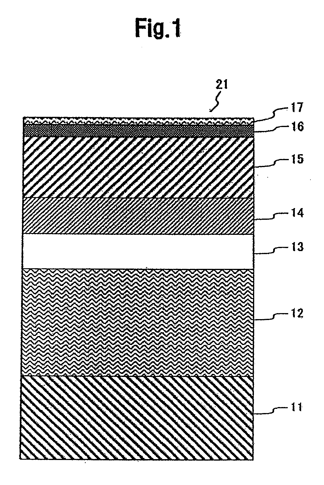
[0063]A multilayer thin film was formed on a cleaned reinforced-glass substrate 11 for a magnetic disk by a DC sputtering method using an in-line type sputtering apparatus. For the multilayer film, a 30-nm-thick AlTi amorphous alloy layer was first formed by using an AlTi50 target (the subscript value shows the atomic percentage, at %, of the element content in the alloy, similarly below) for ensuring adhesion of the thin film to the glass substrate 11. Successively, a three-layered soft-magnetic underlayer 12 was formed by forming a soft magnetic amorphous layer to 30-nm thickness by using an FeCo34Ta10Zr5 target, an antiferromagnetic coupling layer to 0.5-nm thickness by using an Ru target, and another soft magnetic amorphous layer to 30-nm thickness by using the FeCo34Ta10Zr5 target. Further, a seed layer 13 of a two-layered structure was formed by forming in the following order an NiW alloy layer to 7-nm thickness by using an NiW8 target and an Ru layer to 7-nm thickness by usin...

example 2

[0086]The perpendicular magnetic recording medium of Example 2 is characterized in that an intermediate layer is formed by using a target in which a CoCr alloy is mixed with various oxide materials. In Example 2, perpendicular magnetic recording media were formed by using the same materials, structure, and the formation method as those of Example 1 except for the intermediate layer and the seed layer. The magnetic characteristics and recording / reproducing characteristics of the produced samples were measured by the evaluation method shown in Example 1.

[0087]According to the procedures shown in Example 1, the medium was formed first as far as the soft-magnetic underlayer 12. A Ti layer of 8 nm thickness was then formed thereon using a pure Ti target. Then, a Cu layer of 1 nm thickness was formed by using a pure Cu target, and successively, an NiW alloy layer of 7 nm thickness was formed by using an NiW8 target. Thus, the seed layer 13 of a 3-layered stack structure comprising the Ti ...

example 3

[0092]In the perpendicular magnetic recording medium of Example 3, a metal element having the fcc crystal structure by itself was added to the intermediate layer 14. Perpendicular magnetic recording media were formed by the same method as in Example 2 except for the material composition of the targets used upon formation of the intermediate layer 14. Further, the magnetic characteristics (Hc) and recording / reproducing characteristics (SNR) were measured by using the same evaluation method as in Example 1. FIG. 11 is a table showing metal alloys and oxides in the material composition of the intermediate layer targets, the partial pressure of the oxygen gas applied upon formation of the intermediate layer, the coercivity Hc of the magnetic recording layer obtained by magnetic characteristics evaluation, and the SNR obtained by recording / reproducing characteristics evaluation.

[0093]Sample 3-1 to Sample 3-6 shown in FIG. 11 each contain one of the fcc metal elements from among Cu, Ni, P...


PUM

PropertyMeasurementUnit
thicknessaaaaaaaaaa
thicknessaaaaaaaaaa
thicknessaaaaaaaaaa

Abstract

Embodiments of the present invention help allow accurate control of the magnetization reversal in a magnetic recording layer in small reversal units, whereby high-density recording can be achieved. According to one embodiment, by forming an intermediate layer having a granular structure similar to that of the magnetic recording layer below the magnetic recording layer, a continuous crystal grain boundary is formed at the interface between the magnetic recording layer and the intermediate layer, thereby preventing incomplete formation of the crystal grain boundary found in the initial growth layer of the magnetic recording layer. The intermediate layer comprises a non-magnetic alloy comprising Co and Cr as its main components and an oxide such as Al, Cr, Hf. Mg, Nb, Si, Ta, Ti and Zr. Further, the average content of the oxygen element in the intermediate layer is in the range from 6 at % to 20 at %.

Description

CROSS-REFERENCE TO RELATED APPLICATION[0001]The instant nonprovisional patent application claims priority to Japanese Patent Application No. 2007-286391 filed Nov. 2, 2007, which is incorporated by reference in its entirety herein for all purposes.BACKGROUND OF THE INVENTION[0002]Hard disk drives (HDD) have become indispensable information storage apparatuses for computers and various consumer electronics products, particularly, for the purpose of large capacity information storage. Magnetic recoding systems are basically classified into two types of technical methods based on the direction of a magnetization vector in the magnetic recording layer in a magnetic recording medium: one is longitudinal magnetic recording, and the other is perpendicular magnetic recording. The perpendicular magnetic recording system is considered superior in high-density recording to the conventional longitudinal magnetic recording system, since its magnetization state of recorded information is stable d...

Claims


Application Information

Patent Timeline
Patent Type & Authority Applications(United States)
IPC IPC(8): G11B5/127G11B5/667
CPCG11B5/65G11B5/66G11B5/7325G11B5/732G11B5/667G11B5/7379G11B5/737G11B5/7373G11B5/672
Inventor NEMOTO, HIROAKITAKEKUMA, IKUKOTAMAI, ICHIROHIRAYAMA, YOSHIYUKI
Owner WESTERN DIGITAL TECH INC
Why Eureka
Try Eureka