

Perpendicular magnetic recording medium and magnetic recording/reproduction apparatus
- Summary
- Abstract
- Description
- Claims
- Application Information
AI Technical Summary
Benefits of technology
Problems solved by technology
Method used
Image

Examples
example 1
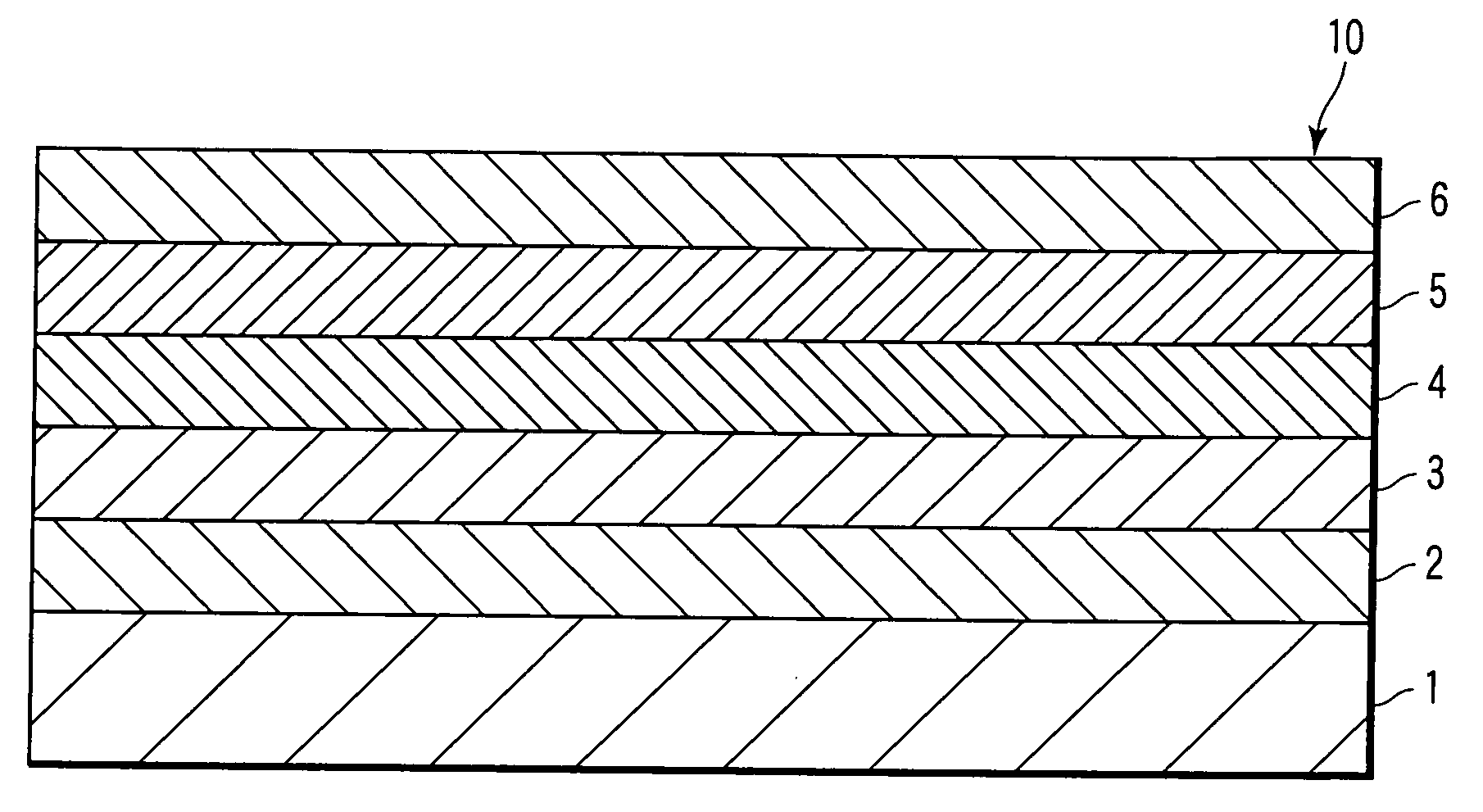
[0061]A nonmagnetic substrate made of a glass substrate for a 2.5-inch magnetic disk was prepared.
[0062]This nonmagnetic substrate was placed in a vacuum chamber having a vacuum degree of 1×10⁻⁵ Pa, and DC magnetron sputtering was performed as follows in an Ar ambient at a gas pressure of 0.7 Pa.
[0063]First, the nonmagnetic substrate was set to oppose a target, and a 25-nm thick CoCrPt ferromagnetic layer was formed as a bias application layer by discharging DC 500 W to a CoCrPt target.
[0064]A 120-nm thick CoZrNb soft magnetic backing layer was formed on the obtained CoCrPt ferromagnetic layer.
[0065]After that, a 5-nm thick Si layer was formed as a nonmagnetic seed layer on the CoZrNb soft magnetic backing layer by discharging DC 500 W to an Si target in an Ar ambient at a gas pressure of 0.1 Pa lower than the normal pressure.
[0066]Then, a 5-nm thick Pd layer was formed as a first nonmagnetic underlayer on the Si seed layer by discharging. DC 500 W to a Pd target in an Ar ambient at...
example 2
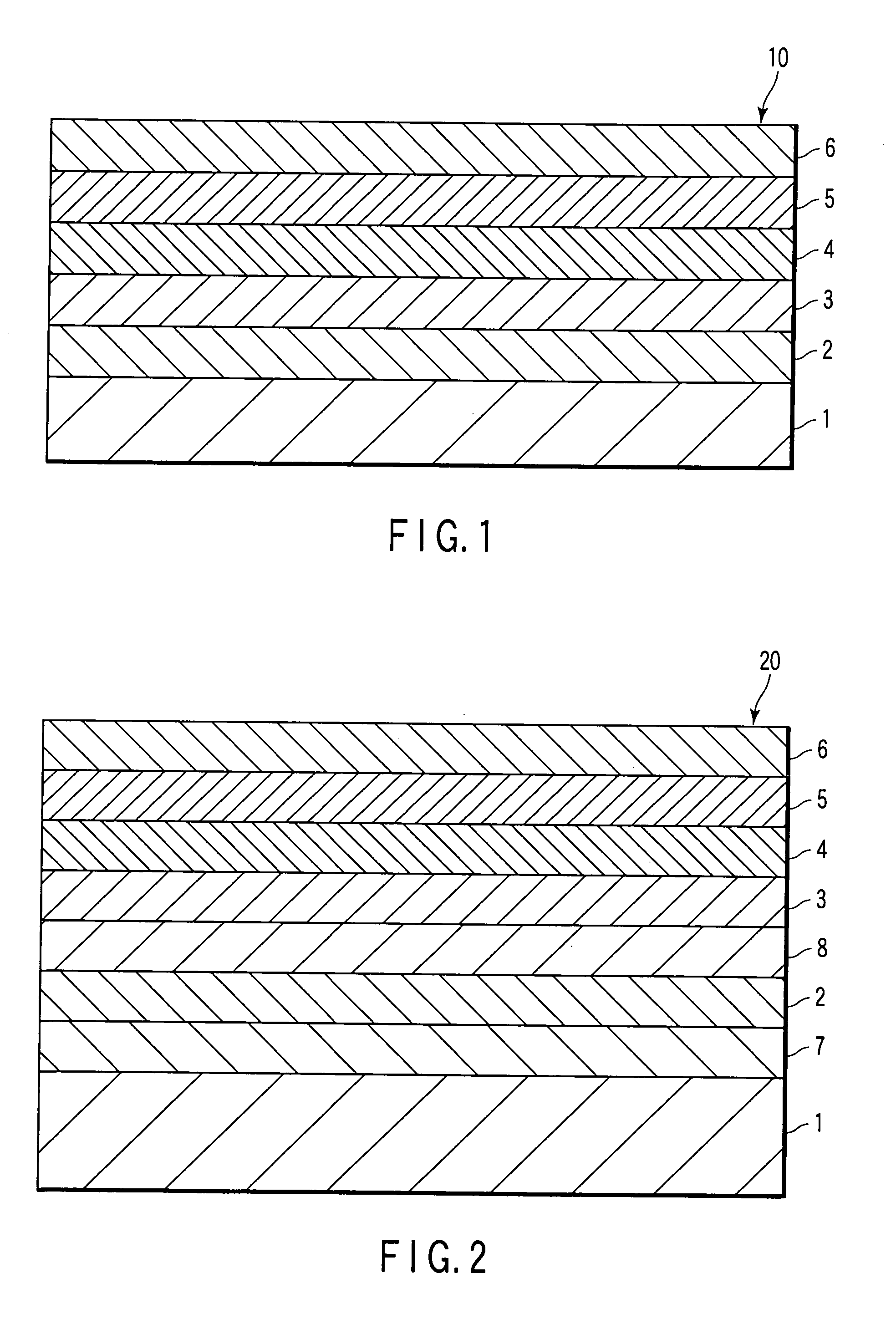
[0133]As the first nonmagnetic underlayer of the medium of the present invention, two types of targets having different composition amounts, i.e., a Pd-34 at % Si target (the soft magnetic layer side) and a Pd-5 at % Si target (the perpendicular magnetic recording layer side) were prepared.
[0134]A perpendicular magnetic recording medium was manufactured following the same procedure as in Example 1 except that the above-mentioned two types of Pd—Si targets, i.e., the Pd-34 at % Si target and Pd-5 at % Si target were used instead of the Pd target as the first nonmagnetic underlayer and no Si seed layer was formed.
[0135]The obtained perpendicular magnetic recording medium had the same layer arrangement as that of the perpendicular magnetic recording medium shown in FIG. 2 except that no Si seed layer was formed and two Pd—Si layers having different compositions were formed as the first nonmagnetic underlayer.
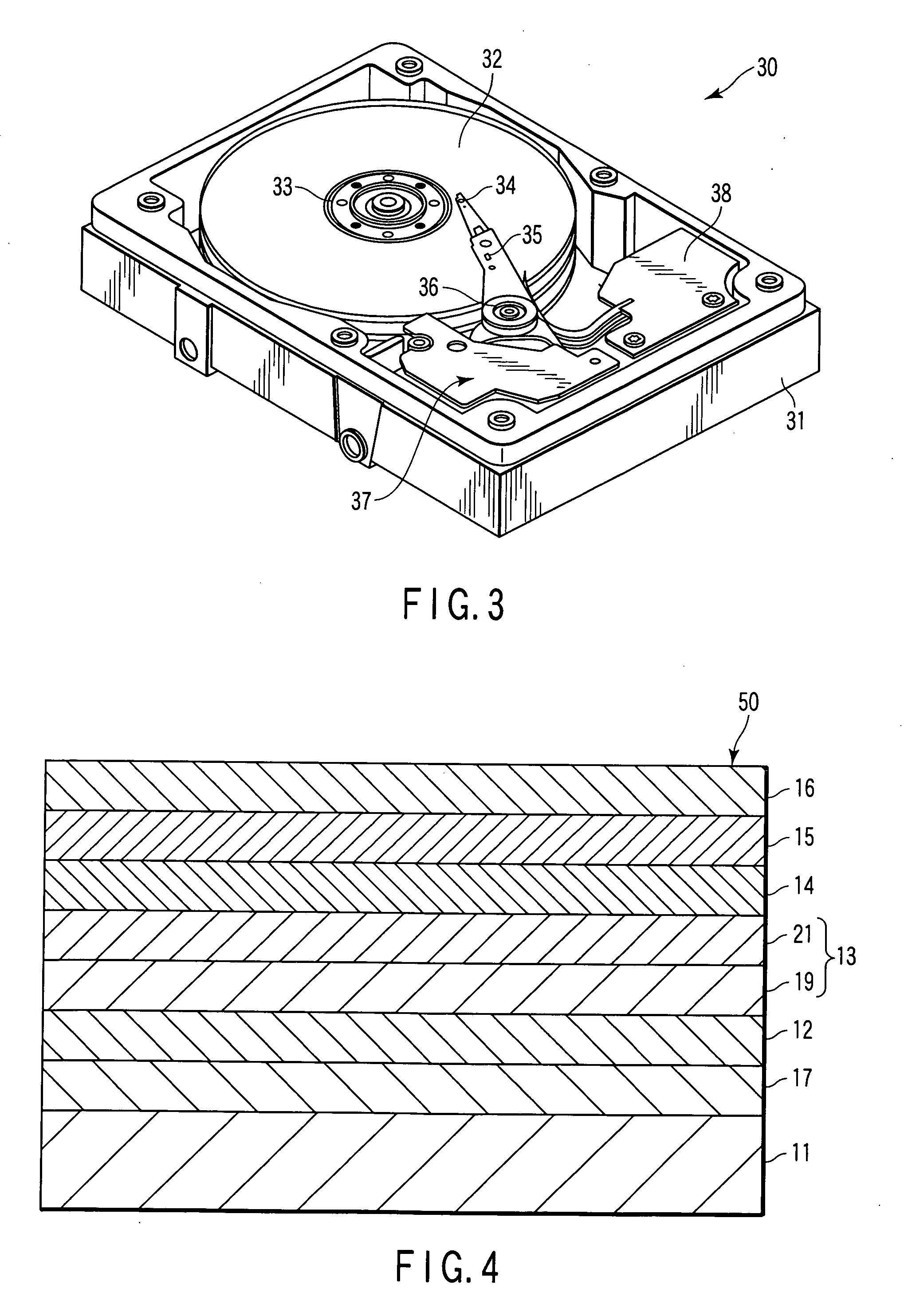
[0136]FIG. 4 is a schematic sectional view showing the arrangement of the obta...
example 3
[0175]A perpendicular magnetic recording medium was manufactured following the same procedure as in Example 1 except that a nonmagnetic seed layer was formed using an Al-45 at % Si target instead of the Si target.
[0176]The obtained perpendicular magnetic recording medium had the same layer arrangement as that of the perpendicular magnetic recording medium shown in FIG. 2 except that the AlSi seed layer was formed instead of the Si seed layer.
[0177]X-ray diffraction measurement was performed on the medium of the present invention.
[0178]As a consequence, an Ru(00.2) peak and CoCrPt (00.2) peak were observed, but no Pd(111) peak was observed. When rocking curve measurement was performed on these peaks, the half-widths of the peaks were 2.70 (Ru) and 3.4° (CoCrPt). This shows that the perpendicular magnetic recording layer had good crystallinity.
[0179]The crystal structure of the medium of the present invention was checked by performing transmission analytical electron microscope (TEM) ...
PUM
 Abstract
Description
Claims
Application Information