Passive electronics components comprising coated nanoparticles and methods for producing and using the same

a technology of electronic components and nanoparticles, applied in the direction of fixed capacitor details, stacked capacitors, fixed capacitors, etc., can solve the problems of increasing the downtime of batch processes, increasing the cost of equipment maintenance, so as to improve the performance and/or increase the performance of passive electronics components, and improve the effect of the mean time to failur

Active Publication Date: 2017-01-26
PNEUMATICOAT TECH LLC
View PDF3 Cites 15 Cited by
  • Summary
  • Abstract
  • Description
  • Claims
  • Application Information

AI Technical Summary

Benefits of technology

[0018]Some aspects of the invention provide a passive electronics component comprising nanoparticles that are coated with a thin film of material. The thin film coating can be an oxidation-resistant material or a reliability-improving material. As used herein, the term “reliability-improving materials” refers to materials that can improve the performance and/or the life span or mean time to failure of the passive electronics component compared to the same passive electronics component in the absence of the thin film coating. In one particular instan

Problems solved by technology

Batch processes have significant inefficiencies when operated at large scale.
One of the disadvantages of batch processes is that the reactor throughput is a function of the total particle mass or volume loaded into a certain sized vessel for a given process, the total process time (up-time), and the total time between processes (down-time) to load, unload, clean, prepare, etc.
Equipment failures and maintenance add to this downtime in batch processes.
Moreover, relatively speaking, batch process equipment tends to be very large and expensive.
The need to operate these processes under vacuum adds greatly to equipment costs, especially as equipment size increases.
Because of this, equipment costs for batch processes tend to increase faster than operating capacity.
Another problem that occurs as the process equipment becomes larger is that it becomes more difficult to maintain uniform reaction conditions throughout the vessel.
It is also difficult to adequately fluidize a large mass of particles, specifically nanoparticles.
Issues such as these can lead to inconsistencies and defects in t

Method used


Image

  • Passive electronics components comprising coated nanoparticles and methods for producing and using the same
  • Passive electronics components comprising coated nanoparticles and methods for producing and using the same
  • Passive electronics components comprising coated nanoparticles and methods for producing and using the same

Examples


examples

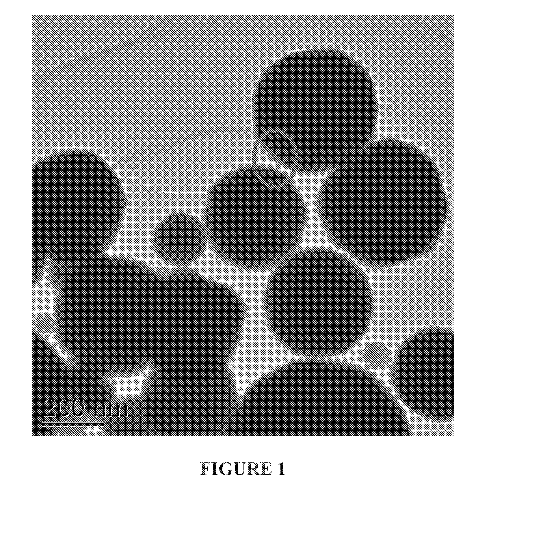
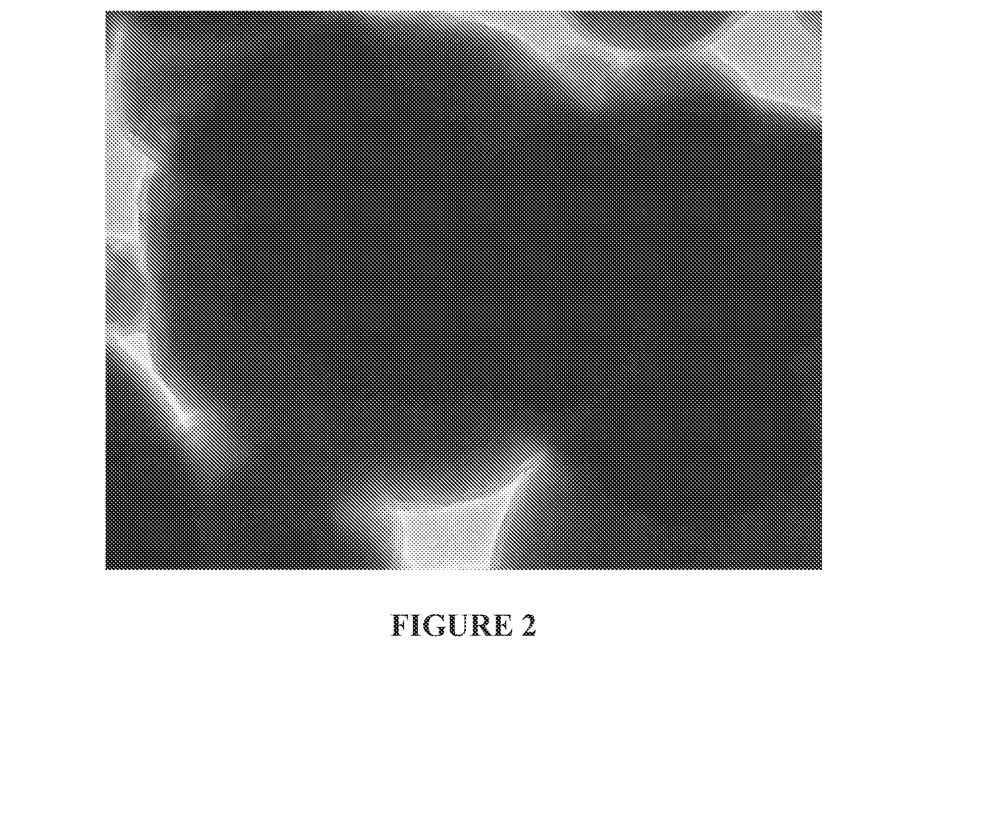
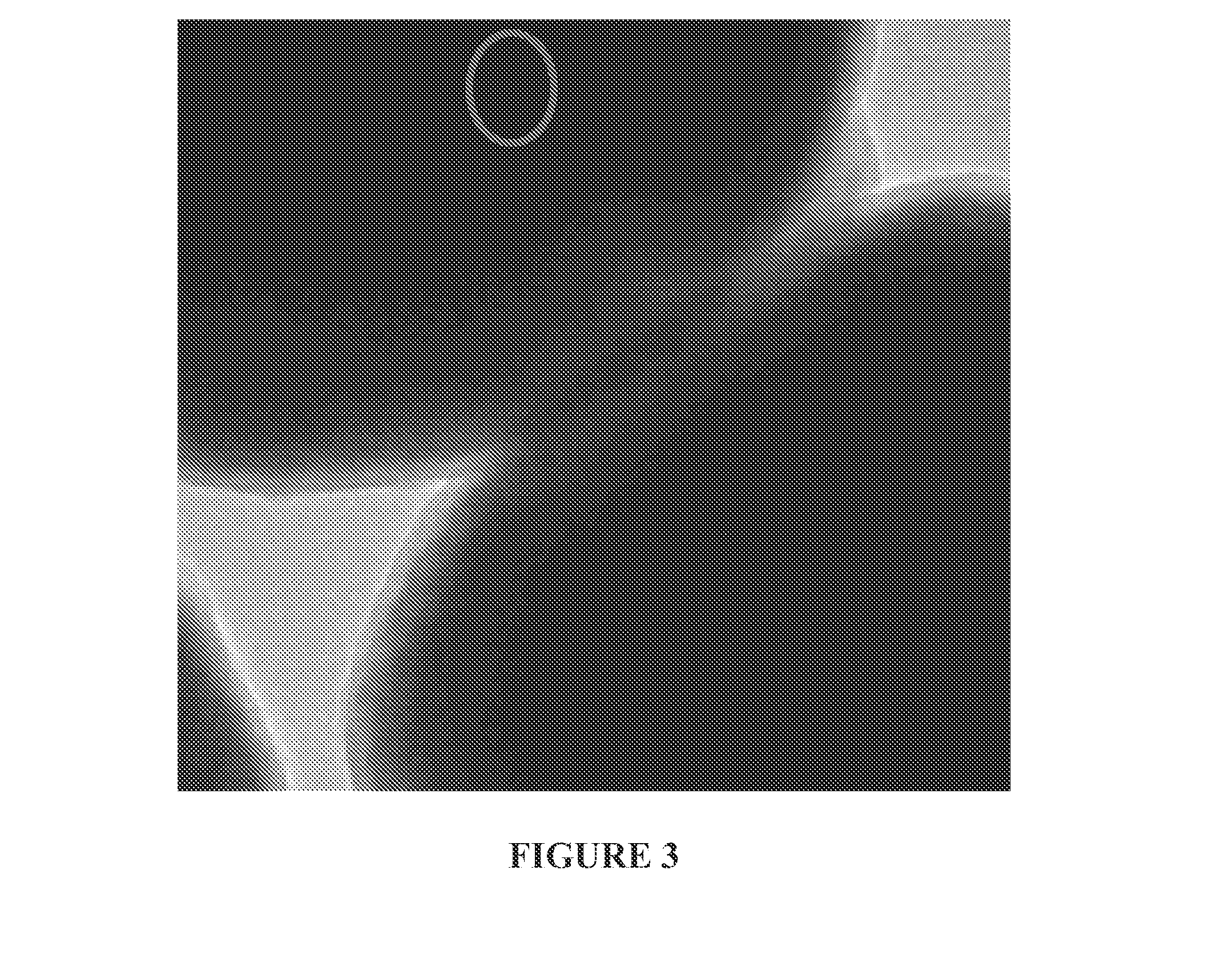
[0066]Metallic copper particles devoid of native copper oxide coating, with and without ALD encapsulation coatings, have been produced in a set of six trials, using two different copper substrates to compare and contrast coating processes: two trials utilized 1-5 micron copper powders that maintained a nanoscale native oxide of copper in the as-received state (substrate A); and two trials utilized the decomposition of a copper oxalate powder in a fluidized bed reactor (substrate B). For substrates A and B, the following processes were run:[0067](1) Forming gas exposure at elevated temperature (450° C.) for 60 minutes;[0068](2) The process of (1) followed by a 3 nm ALD coating of Al2O3; and[0069](3) A first coating of a 5 nm aluminum alkoxide layer via the Molecular Layer

[0070]Deposition (MLD), which results in a mesoporous Al2O3 coating during an elevated temperature organic burn-out step. Subsequently the process of (2) was followed, inclusive of the process of (1) as described abo...


PUM

PropertyMeasurementUnit
Temperatureaaaaaaaaaa
Fractionaaaaaaaaaa
Thicknessaaaaaaaaaa

Abstract

The present invention provides various passive electronic components comprising a layer of coated nanoparticles, and methods for producing and using the same. Some of the passive electronic components of the invention include, but are not limited to conductors, resistors, capacitors, piezoelectronic devices, inductors and transformers.

Description

CROSS-REFERENCE TO RELATED APPLICATION[0001]This application claims the benefit of U.S. Provisional Application No. 61 / 973,352, filed Apr. 1, 2014, the disclosure of which is incorporated herein by reference in its entirety.FEDERAL FUNDING STATEMENT[0002]This invention was made with government support under Contract No. DE-SC0010239 awarded by the Department of Energy. The Government has certain rights in this invention.FIELD OF THE INVENTION[0003]The present invention relates to various passive electronic components comprising a layer of coated nanoparticles, and methods for producing and using the same.BACKGROUND OF THE INVENTION[0004]The incorporation of particles from millimeter-scale down to nanometers in size is ubiquitous in end-use products produced in industrial-scale quantities. A significant percentage of the particles used across all industries require that the surfaces be coated with a shell, layer, film, or other coating, ranging from sub-nanometer to hundreds of micro...

Claims


Application Information

Patent Timeline
IPC IPC(8): C23C16/44H01G4/008C23C16/455B22F1/00B22F1/02B22F1/054B22F1/16
CPCC23C16/4417B22F1/0003H01G4/0085C23C16/45525B22F1/02H01G4/30H01G4/1227B22F1/16B22F1/054B22F1/056B22F1/00
Inventor KING, DAVID M.LICHTY, PAUL
Owner PNEUMATICOAT TECH LLC
Why Eureka
Try Eureka